Composite simulation is crucial because it lets engineers explore designs, optimize performance, and spot failures digitally, saving tons of time and money compared to physical testing. It's challenging due to anisotropy, modeling delamination, and high computational cost.
Comprehensive Guide to Composite Materials and Simulation
Matt Veidth | CAE Assistant
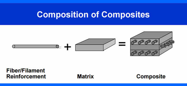
Ever wondered how some materials can be incredibly strong yet surprisingly light? Well, that's where composite materials come in! Basically, they're engineered by combining two or more different materials, like a matrix and a reinforcement. The goal is to create something with far superior properties than either component could offer alone. Each part keeps its identity but works together to boost overall strength and performance. They are especially loved for their amazing strength-to-weight ratio and flexibility in design.
For instance, think of Carbon Fiber Reinforced Polymer (CFRP) in aircraft; it provides immense strength while being much lighter than steel. You'll also find composites in wind turbine blades, sporting goods, automotive parts, and even bulletproof armor.
Now, to make sure these complex materials perform perfectly, engineers use composite simulation. This is a crucial process that lets them quickly explore designs, fine-tune performance, and spot potential failure points. It's much faster and more cost-effective than building and testing physical prototypes. Imagine simulating how a rocket nozzle made of Carbon-Carbon composites will withstand extreme temperatures without actually needing to build one every time. This approach significantly cuts down on testing time and material waste.
What are composite materials and why are they preferred over traditional materials like metals?
Composite materials are engineered by combining two or more distinct materials, such as a matrix and a reinforcement, to achieve superior properties that neither component could offer alone.
Unlike alloys, the individual materials in a composite retain their identity but work synergistically to enhance the overall strength and performance. They are particularly favored for their excellent strength-to-weight ratio and design flexibility. For instance, in aerospace applications, composites like Carbon Fiber Reinforced Polymer (CFRP) provide the necessary strength while being significantly lighter than steel, which is too heavy and lacks the required flexibility. This enables manufacturers to tailor materials with precise qualities for specific structural purposes.
How do composites differ from metals in terms of behavior and failure modes?
Composites exhibit fundamentally different behaviors compared to metals. Metals are typically isotropic, meaning their properties are uniform in all directions. In contrast, composites are anisotropic, with their strength and stiffness varying depending on the fiber orientation.
This anisotropy contributes to their high strength-to-weight ratio but also makes their behavior more complex. Furthermore, metals are ductile, deforming plastically before breaking and often showing warning signs. Composites, however, are generally more brittle and can fail suddenly through multiple mechanisms, including fiber breakage, matrix cracking, fiber-matrix debonding, or delamination between layers. These mechanisms can occur individually or simultaneously, necessitating advanced failure criteria in their analysis.
What are the main ways composites are classified, and what are some practical examples of each?
Composites are commonly classified based on their matrix material or reinforcement material. Based on the matrix material, they include:
- Organic Matrix Composites (OMCs): Often Polymer Matrix Composites (PMCs) like fiberglass or carbon fiber reinforced polymers (CFRP), used in aerospace, automotive, sporting goods, and medical implants. Carbon-Carbon composites (carbon fibers in a carbon matrix) are also OMCs, known for high-temperature resistance in rocket nozzles and furnace fixtures.
- Metal Matrix Composites (MMCs): Fibers or particles dispersed in a metallic matrix (e.g., steel, aluminum). They offer high specific strength and stiffness, fire resistance, and suitability for harsh conditions, found in tank armors, automotive engines, and aircraft landing gear.
- Ceramic Matrix Composites (CMCs): Both matrix and reinforcement are ceramic, offering high creep resistance, thermal shock resistance, and performance in extreme temperatures for turbine blades, bulletproof armor, and rocket components.
Based on the reinforcement material, they include:
- Particle Reinforced Composites: A matrix strengthened by dispersed particles, like concrete (large particles) or dispersion-strengthened composites (fine particles), used in road surfaces and particle board.
- Flake Reinforced Composites: Flat reinforcements in a matrix, offering high out-of-plane flexural modulus, with examples like glass, mica, or aluminum flakes.
- Fiber Reinforced Composites (FRCs): Matrices reinforced by fibers, which can be continuous (unidirectional, bidirectional, woven) or discontinuous (short fibers, aligned or random). Examples include GFRP and CFRP, widely used in sports equipment, aircraft, and wind turbine blades.
- Nanocomposites: Components at the nanoscale (less than 100 nm), which can significantly improve properties like elastic modulus and barrier transmission rates, used in military packaging.
What is multiscale composite modeling, and why is it necessary for effective composite analysis?
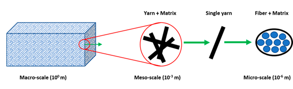
Multiscale composite modeling is an approach that connects the behavior of composite materials across different length scales – micro, meso, and macro – to fully understand their performance. Composites are not uniform like metals; their fibers, matrix, and interfaces interact differently at various scales.
- Microscale (Fiber and Matrix Level): Focuses on individual fibers, the matrix, and their interface to predict effective material properties, study fiber-matrix debonding, and analyze defect influence. It's computationally intensive and often used to generate data for higher-level models.
- Mesoscale (Ply and Laminate Level): Examines plies and laminates, including fiber orientation and stacking sequence, to predict delamination and study ply interactions. This is where progressive damage modeling often begins.
- Macroscale (Structural Level): Models the entire structure (e.g., an airplane wing) by treating the material as a homogenized equivalent, using properties derived from lower scales. This scale is common for full structural analysis, global failure modes, and design optimization in FEA software. This comprehensive approach is essential because it allows engineers to accurately predict how microscopic interactions influence macroscopic structural behavior, leading to more reliable designs.
Why is composite simulation important, and what are some common challenges engineers face?
Composite simulation is crucial because it enables engineers to rapidly explore designs, optimize performance, and identify potential failure modes much faster and more cost-effectively than relying solely on physical testing.
It significantly reduces prototype counts, testing time, and material waste.
However, composite simulation presents several challenges:
- Anisotropy: Composites' directional-dependent properties require precise definition of fiber orientation and ply angles, as errors can lead to inaccurate stiffness and failure predictions.
- Delamination and Interlaminar Damage: Layers can separate under various loads, and modeling this requires specialized techniques like cohesive elements, which add complexity and computational cost.
- High Computational Cost: Detailed microscale models or 3D solid elements can be very expensive in terms of CPU time and memory, necessitating strategies like homogenization, shell approximations, or submodeling to balance fidelity and cost.
- Other Challenges: These include finding reliable material properties, accurately representing manufacturing defects (e.g., voids, fiber waviness), and predicting fatigue life under complex cyclic loading.
What key concepts are essential for accurate composite simulation, especially regarding failure?
Before running a composite simulation, understanding core concepts is vital for accurate analysis, particularly concerning failure.
- Failure Criteria: Unlike metals with predictable yielding, composites fail in multiple ways. Engineers use specific criteria to predict different failure modes:
- Tsai-Hill & Tsai-Wu Criteria: General-purpose criteria for quick estimates of laminate failure under combined stresses. Tsai-Wu improves on Tsai-Hill by including interaction terms.
- Hashin Criterion: Distinguishes between fiber failure and matrix failure, offering more accuracy for progressive damage.
- Puck Criterion: Excels at predicting inter-fiber failure (IFF), delamination, and transverse cracking.
- Damage Simulation: Addresses specific damage mechanisms that can lead to sudden failure:
- Delamination: The separation of layers, which significantly reduces stiffness and can cause catastrophic failure.
- Impact: Modeling low-velocity (e.g., tool drops) or high-velocity (e.g., bird strikes) impacts to assess hidden damage like fiber breakage and matrix cracking.
- Blast and Extreme Loads: Simulating energy absorption and progressive failure under explosive conditions.
- Fatigue Simulation: Predicts how composites behave under millions of load cycles. Unlike metals with clear fatigue limits, composites exhibit complex fatigue behavior, with different failure modes depending on fiber orientation and loading type. This is crucial for predicting service life in aerospace, automotive, and wind energy applications.
What software tools are commonly used for composite simulation, and how does one choose the right one?
Several software tools are widely used for composite simulation, each with its strengths:
- Abaqus (SIMULIA): Excellent for advanced composite analysis, including layered composites, nonlinear behavior, and advanced failure criteria (Hashin, Puck, Tsai-Wu). It provides strong support for cohesive elements and delamination modeling and is popular in both academia and industry for detailed composite workflows. The Composite Simulation blog from CAE Assistant would be great help.
- Ansys: Strong in integrated multiphysics simulations, enabling coupling of structural, thermal, and manufacturing analyses. It is useful for full-product workflows where composite parts interact with other systems and offers broad multiphysics capabilities.
- Altair: Focuses on optimization, lightweighting, and manufacturability checks (e.g., forming, drape). It is ideal when design optimization needs to be coupled with composite performance.
- Open-source options (e.g., CalculiX, PrePoMax, MOOSE): These tools offer lower costs but may require more manual setup and scripting. CalculiX, for instance, supports many FEA tasks and uses an Abaqus-like input format, often used in research and education.
The choice of tool depends on specific project goals, budget, and the team's skillset. Abaqus or Ansys are recommended for deep, validated composite features like ply-by-ply failure and delamination, while Altair is suitable for optimization and manufacturability. Open-source tools are a good option for tight budgets or extensive customization.
What are the general steps involved in running a composite simulation in Abaqus?
Running a composite simulation in Abaqus involves a structured workflow to ensure accuracy:
- Collecting Composite Material Data (Step 0): Before starting, gather essential material properties, including elastic constants (E1, E2, G12, ν12), ply thickness, and strength values. This data is fundamental for realistic simulations.
- Defining Composite Material Properties (Step 1): Input the orthotropic material properties, including elastic and strength values, into Abaqus. These values will be used in subsequent failure criteria.
- Creating a Composite Layup (Step 2): Define the laminate structure by specifying the sequence, orientation, and thickness of each ply. Fiber direction is critical as it directly influences stiffness and strength.
- Applying Loads and Boundary Conditions (Step 3): Set up the external loads (e.g., tensile, shear, bending, impact) and boundary conditions that accurately reflect the real-world operational environment of the structure.
- Choosing the Right Analysis Type (Step 4): Select the appropriate analysis type in Abaqus, such as static loading, buckling, impact, or fatigue, based on the specific problem being investigated.
- Running and Interpreting Results (Step 5): Execute the simulation and then analyze the output, including stresses, strains, and failure indices. Failure criteria like Tsai-Wu or Hashin are applied here to determine if and where the laminate fails.
- Validating with Experiments (Step 6): Crucially, simulation results must be validated against physical experiments (e.g., tensile, shear, or delamination tests) to confirm that the FEA model accurately represents the physical behavior of the composite.
Recap
So, composite materials are engineered by combining distinct materials like a matrix and reinforcement to achieve superior properties, such as in Carbon Fiber Reinforced Polymer (CFRP) for aircraft, making them lighter yet stronger than steel. Unlike metals, which are isotropic and deform, composites are anisotropic, with properties varying by fiber orientation, and can fail suddenly through mechanisms like delamination. They're classified by matrix (e.g., Organic Matrix Composites like CFRP) or reinforcement (e.g., Fiber Reinforced Composites in wind turbine blades).
Composite simulation is crucial because it lets engineers explore designs, optimize performance, and spot failures digitally, saving tons of time and money compared to physical testing. It's challenging due to anisotropy, modeling delamination, and high computational cost. Accurate simulation needs concepts like failure criteria (e.g., Hashin for fiber/matrix failure) and damage simulation (like impact analysis). Tools like Abaqus help define material properties, create layups, apply loads, run analyses, and interpret results, which are then validated with experiments for real-world accuracy.
The content & opinions in this article are the author’s and do not necessarily represent the views of ManufacturingTomorrow
Comments (0)
This post does not have any comments. Be the first to leave a comment below.
Featured Product