Preventing Part Movement During CNC Machining
Whether machining large metal blocks or delicate plastic parts, maintaining the stability of the workpiece throughout the process is critical. This article explores why parts move during CNC machining, what consequences can arise, and what best practices and strategies can be used to ensure absolute part security.
Why Do Parts Move During CNC Machining?
Common causes include:
Inadequate or uneven clamping force
Poor fixture design or incorrect fixturing for the part geometry
Vibrations or chatter due to machine instability
Incorrect alignment or setup error
Thermal expansion or material deflection during cutting
Risks and Consequences of Part Movement
Even the slightest movement during cutting can lead to:
Loss of dimensional accuracy
Surface finish degradation
Out-of-tolerance features or failed QA inspections
Broken tools or damaged fixtures
Increased scrap rate and production delays
In high-precision industries like aerospace or medical manufacturing, part stability is non-negotiable. Machining a high-value part with improper fixturing can lead to major financial losses or safety risks.
Best Practices to Prevent Part Movement During CNC Machining
1. Select the Right Workholding System
Not all parts require a vise. Depending on geometry, size, and material, better options may include:
Soft jaws or custom-machined jaws that conform to irregular shapes
Fixture plates with dowel pins for repeatable location
Vacuum fixtures for thin or non-rigid parts
Magnetic workholding for ferrous components
Collet chucks for round bar stock or turned parts
Ensure the selected method is appropriate for both clamping force and accessibility of the cutting area.
2. Apply Uniform Clamping Pressure
Unbalanced clamping leads to tilting, vibration, or movement during cutting. Use torque-limiting tools or calibrated systems to apply consistent pressure across multiple clamps or fasteners. For large parts, distribute clamps evenly across the surface to avoid bowing or distortion.
3. Use Dowel Pins or Locating Stops
Clamping alone isn't enough. Clamps apply pressure but do not define position—especially under lateral cutting forces. Dowel pins, hardened stops, or precision shoulders should be used to mechanically constrain the part and absorb shear forces.
In modular setups, locating features on fixture plates ensure repeatability and reduce setup time while preventing drift.
4. Match Fixturing to Cutting Direction
Plan clamping based on expected cutting forces. For example, if most forces will act from right to left, clamps and stops should be oriented to resist motion in that direction. Fixturing should not only hold the part down but also resist horizontal push.
5. Minimize Unsupported Areas
Avoid allowing thin walls or overhanging features to vibrate or flex during cutting. Add supports or soft backing materials (e.g., sacrificial blocks or wax) beneath vulnerable regions. Unsupported areas are prone to deflection and can create poor surface finishes or dimensional errors.
6. Use High-Quality Fixtures with Rigid Construction
Fixtures should be designed for rigidity. Flexible or worn-out fixtures can amplify vibration and allow the part to shift. Use hardened steel contact points, precision-machined plates, and robust fasteners to ensure system stability.
For multi-part fixturing, ensure every cavity offers the same level of repeatable force and alignment. Modular fixturing systems often make it easier to build consistent setups.
7. Consider Fixturing for Heat and Expansion
For long or thin parts, thermal expansion can cause material to warp or shift during machining. Leave room in the fixturing to allow for thermal movement, or use low-stress clamping systems that won't restrain natural expansion and cause warping.
8. Use Workpiece Probing and Verification
Before starting full machining, use touch probes or laser measurement systems to verify part alignment and positioning. Mid-process probing can detect if a part has moved, allowing for corrective action before the part is ruined.
Advanced Tips for High-Precision Machining
Use zero-point fixturing systems for fast and repeatable part swaps without affecting alignment.
Employ in-process force monitoring to detect vibration or movement in real time.
Implement simulation and FEA during fixture design to predict weak points or stress zones.
For delicate materials (plastics or composites), use non-marring clamps or vacuum systems to reduce deformation.
Conclusion
In CNC machining, securing the part is just as critical as programming the toolpath. Preventing part movement means fewer errors, higher accuracy, longer tool life, and less downtime. Whether you're working with large castings or delicate prototypes, thoughtful fixturing and setup practices are essential to stable, high-quality machining.
As machines become faster and more capable, the margin for error shrinks—and so the importance of secure, intelligent workholding continues to grow. Investing time in preventing part movement pays off in the form of better parts, fewer mistakes, and a more efficient machining operation overall.
Featured Product

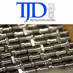
T.J. Davies' Retention Knobs
Our retention knobs are manufactured above international standards or to machine builder specifications. Retention knobs are manufactured utilizing AMS-6274/AISI-8620 alloy steel drawn in the United States. Threads are single-pointed on our lathes while manufacturing all other retention knob features to ensure high concentricity. Our process ensures that our threads are balanced (lead in/lead out at 180 degrees.) Each retention knob is carburized (hardened) to 58-62HRC, and case depth is .020-.030. Core hardness 40HRC. Each retention knob is coated utilizing a hot black oxide coating to military specifications. Our retention knobs are 100% covered in black oxide to prevent rust. All retention knob surfaces (not just mating surfaces) have a precision finish of 32 RMA micro or better: ISO grade 6N. Each retention knob is magnetic particle tested and tested at 2.5 times the pulling force of the drawbar. Certifications are maintained for each step in the manufacturing process for traceability.
