Make sure your drawing undergoes all quality assurance and approval procedures. A drawing that is easy to follow and clearly defines your requirements is one of the first steps to a successfully manufactured part.
How to Create A Good Technical Drawing
Article from | Xometry
Introduction
.jpg) Two-dimensional technical drawings have been part of the engineering process since before the printing press. According to Interesting Engineering, perspective drawing was invented in the 1300s. The first technical drawings for manufacturing were perspective drawings of real objects. Centuries later, the invention of descriptive geometry (1765) and orthographic projection (1770), helped engineers give visual form to their ideas. From this point until the introduction of 3D CAD modeling in the 1980s, 2D technical drawings were the main way engineers documented their designs.
Two-dimensional technical drawings have been part of the engineering process since before the printing press. According to Interesting Engineering, perspective drawing was invented in the 1300s. The first technical drawings for manufacturing were perspective drawings of real objects. Centuries later, the invention of descriptive geometry (1765) and orthographic projection (1770), helped engineers give visual form to their ideas. From this point until the introduction of 3D CAD modeling in the 1980s, 2D technical drawings were the main way engineers documented their designs.
A Paradigm Shift to CAD-Driven Manufacturing
Today, most projects are designed as 3D CAD files from the start. Manufacturers use digital tools to generate manufacturing commands for computer-controlled machinery such as CNC machines or 3D printers. This planning software, such as CAM, uses the 3D model to create toolpaths and movements for the manufacturing process. The technical information captured on a drawing or print might only be used as a reference rather than a definitive guide for manufacturing, especially since some of the standard dimensions may not be included in the actual print drawing. Instead, it is assumed that the 3D CAD program would guide those feature sets, or dimensions, not shown on a drawing.
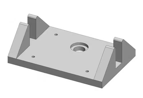
Example of a 3D CAD model.
The omission of non-critical measurements on modern prints signifies a paradigm shift in manufacturing. The industry has reversed its mentality; technical drawing prints used to be considered the authoritative documents, with CAD files being supplemental. Now CAD takes the lead position, and the prints have become supplemental. In the event of a conflict between CAD and drawing, the CAD model now typically takes precedence.
How to Create a Technical Print from Scratch
It is important to remember that technical drawings for manufacturing are critically important documents—they inform every machine-cut, forming, and critical feature during production. Mistakes that arise from ambiguities in the drawing may cost extra money when a part has to be redone or reworked, and may lead to project delays. Many machine shops refuse to take on jobs that have poor drawings with missing dimensions, unclear design features, or sub-standard detailing. When working with a manufacturer through a manufacturing shop consolidator like Xometry, this can lead to more back-and-forth between all parties.
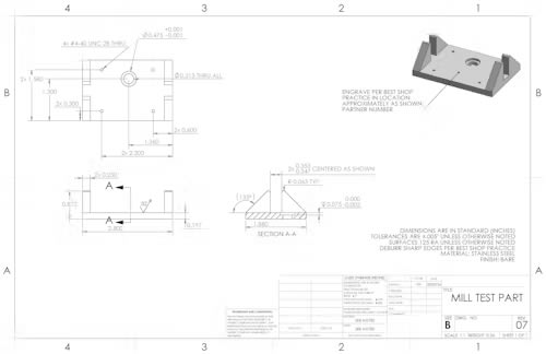
Example of a Technical Print
To reduce the chances of having drawings returned from the manufacturer with many redlines and substitution requests, it is essential to create clear technical drawings the first time.
Here is a best-practices guide to help engineers create clear and professional manufacturing drawings the first time around. These best practices apply to 2D drafting and creating technical drawings from a 3D model.
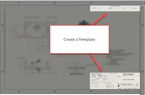
1. Create a template.
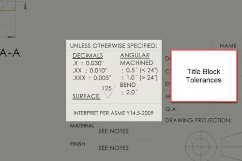
Create a single template that can be used for detail and assembly drawings compliant with ASME or ISO standards (depending on location). The title block in the bottom right corner must include company or organization information, names of the people responsible for the drawings (designer, checker, approver), drawing title/name, revision reference, sheet size, view alignment convention, and primary scale. Also, include a space in the title block to specify the default tolerances that are not displayed alongside the dimensions on the drawing. A parts list can be added above the title block to list any extra parts or components needed for assembly, with reference to the drawing for each piece using the drawing’s title or page number.
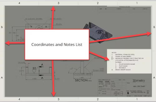
2. Add coordinates and a notes list.
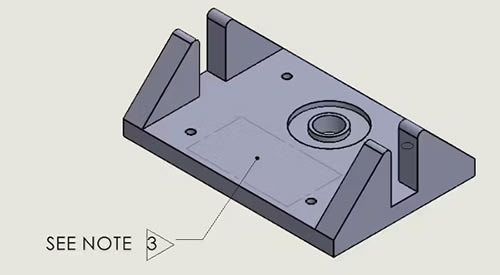
When creating large or complex technical drawings for manufacturing, it is good practice to include coordinate divisions along the border as reference points when discussing a dimension or feature. Retain a space for a notes list in the top left corner of the page to display materials and coding specifications, relevant standards, special instructions for manufacturing, and any other important information. Notes specific to a feature or the print can be referenced in the part drawing using triangular flags with the appropriate note number.
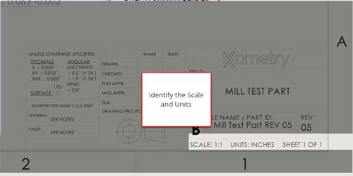
3. Check your scale and units.
Ensure that the drawings fit on the page and that the dimensions will be clearly seen in each view. If you plan on sending the part to be manufactured abroad, it is best practice to use the metric system for dimensions. In the US, it’s best practice to use imperial measurements since most manufacturers program their machines using the imperial system, but all manufacturers can interpret both units of measurement. When in doubt, use both sets of measurements with a dual-dimension layout.
4. Ensure correct tolerances.
Generally, it is best to choose reasonable tolerances for most modern CNC machines, typically around +/- 0.005” for distance dimensions. Xometry references general tolerances for different processes in its manufacturing standards. Tolerances can be adjusted according to the type of designed parts and the production method, but adhering to general tolerances on parts can help manage design expectations and reduce costs. Tolerances more narrow than the general range are considered “tight tolerances,” and those wider than the general range are “loose tolerances.”
5. Create templates for subsequent sheets.
In preparation for revisions, create a template that has a continuation title block and a revision table in the top right corner which displays the revision date, the reason for the change, and the name of the person who made the revisions. The first page and subsequent pages of drawings should identify the page number and total number of pages in the lower right.
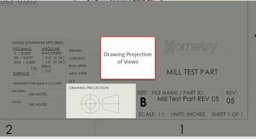
6. Ensure views align with the projection view.
Once you start drawing, it is important to use the correct projection alignment. The person fabricating the part will use this orientation during manufacturing, so make sure that all the views follow the alignment convention that is specified in the title block. In the US, third angle projection is typical whereas in Europe, first angle projection is more common.
7. Include an isometric view if possible.
If there is room on the page, it is good practice to include a 3D isometric view to help the machinist when manufacturing the part. These don’t need to be in the same alignment as the orthographic views but make sure that they are drawn from the correct corner for the orientation you want to show. Do not include dimensions in the isometric drawing (as the scale is different), but notes can be included. Beyond adding more information about the part in 3-dimensions, isometric views can show valuable information such as the installation direction for inserts or pins on assemblies.
8. Limit the number of hidden lines.
An excess of hidden lines and tangent lines can reduce the clarity of a drawing. Only include essential hidden lines. Others can be noted and shown clearly on an isometric drawing or detailed in an exploded view for smaller features.
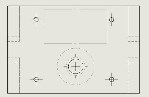
The dotted lines above, are unnecessary hidden lines because the features are highlighted in other drawing views.
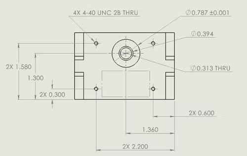
9. Ensure clarity of dimensions.
Make sure dimensions are placed outside of the view and that dimension lines do not cross each other. For clarity, be careful not to duplicate dimensions that may be called out in other views or inherent in a 3D model under title block tolerances. Dimension critical areas, reference dimensions, any GD&T requirements, threads, surfaces, etc. Arcs greater than 180 degrees should be dimensioned by diameter. Arcs less than 180 degrees (e.g. fillets) should be indicated by their radius. If two dimensions meet at a right angle, there is no need to include an angle dimension. Informational dimensions that do not affect the part can be included for reference (e.g. total length which combines several smaller dimensions) but should be in parentheses.
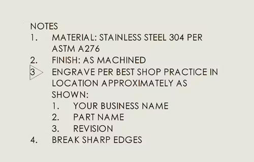
10. Include full specifications for materials and surface finishes.
It is not enough to just list the type of metal. For example, Stainless Steel 304 has four different ASTM specifications, depending on the application. Any special instructions for surface finishing should also be clarified, including edge breaks and deburring. Include these details in the notes section of the drawing.
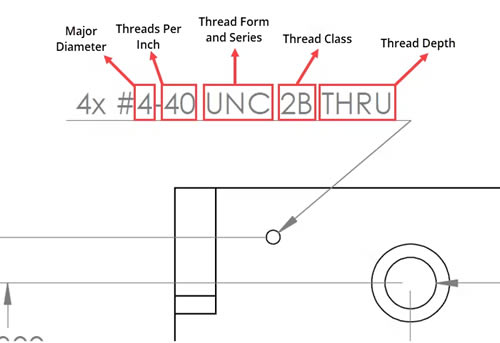
11. Call out threads with complete thread specifications.
Threads can be manufactured in various classes, fits, and specifications to suit the intended application. Therefore, calling out threaded features using complete thread specifications is essential. At a minimum, the thread form, series, major diameter, threads per inch, class of fit, and depth should be specified. It is also recommended to use standard threads; that way, readily available tooling can be used. When an entirely custom thread is required, use a detail view to define the thread form fully.
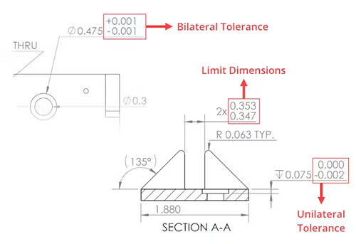
12. Use the appropriate type of linear tolerance.
In manufacturing, some degree of variation between parts is unavoidable. That is why engineers use tolerances to help manufacturers understand how much variation is acceptable for a particular feature or dimension; that way, the part can be made to maintain form, fit, and function. When it comes to linear tolerances, three main types of tolerances can be used:
- Bilateral Tolerances - The variance from the nominal dimension can occur in positive and negative directions. (e.g., ±0.005")
- Unilateral Tolerances - The variance from the nominal dimension is allowed to occur in only one direction. (e.g., +0.005" / - 0.000")
- Limit Dimensions - Stacked dimensions that show the largest and smallest values allowed; any value between these is acceptable. (e.g., 0.525" / 0.520" )
Bilateral tolerances are most common since they are typically used when defining a drawing's general tolerances. Use bilateral tolerances when you can for linear dimensions. Unilateral tolerances and limit dimensions can help call out critical fit dimensions and tight toleranced features in your drawing; however, avoid using them unnecessarily to keep the drawing clear and legible.
13. Control geometric features with GD&T.
GD&T, or Geometric Dimensioning and Tolerancing, is another way engineers and designers communicate their requirements to manufacturers. In addition to tolerance values, GD&T uses symbols, datums, and geometric characteristics to define a feature's acceptable amount of variation. It is beneficial in more complex parts where tightly controlling the geometry is needed. There are a few different kinds of geometric tolerances:
- Form Tolerance - Defines permissible deviations from the ideal shape of a feature. This type of tolerance does not require a datum.
- Orientation Tolerance - Refers to the shape of a feature based on a datum. A datum is required for this type of tolerance.
- Location Tolerance - Defines a feature's position about a datum, typically used in defining hole locations. A datum is needed for location tolerances.
- Run-out Tolerance - Defines the deviation allowed when a feature is rotated around its centerline. Datums are required for this tolerance type.
- Profile Tolerance - Defines the acceptable deviation of a profile line or plane. Profile tolerances do not require datums.
The symbols and methodologies around GD&T are standardized and should be used correctly to avoid confusion with the manufacturer. While geometric dimensioning and tolerancing can be helpful, be sure you are also not over-defining your drawing, which can make your drawing challenging to interpret.
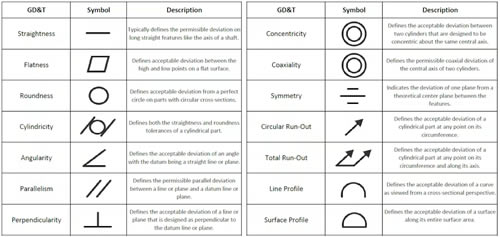
GD&T Symbols Table
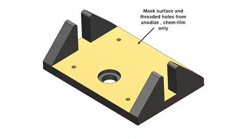
14. Call out finishing requirements clearly.
It can be challenging for a manufacturer or post-processor to follow complex finishing or masking requirements with notes alone. The best practice for parts that require specific areas or features to be masked is to include color-coded views that provide additional guidance. Cross-hatching can also be used in place of color-coded views. For finishing processes with specifications, such as anodizing, it is also helpful to include the specification in your call-out. The key takeaway with post-processing requirements is to do your best to ensure the requirements are clearly communicated and remove room for ambiguity.
Summary
Overall, clarity is the most important factor in any technical drawings for manufacturing. Take the time to ensure that every detail is clear and the drawing complies with the accepted standards. Additionally, make sure your drawing undergoes all quality assurance and approval procedures. A drawing that is easy to follow and clearly defines your requirements is one of the first steps to a successfully manufactured part.
Once your drawing and 3D CAD files are ready, you can upload them into the Xometry Instant Quoting Engine® to get an instant quote!
The content & opinions in this article are the author’s and do not necessarily represent the views of ManufacturingTomorrow
Featured Product