EtherCAT is proven to optimize machine performance with its deterministic performance, flexible topology, and diverse set of features. To better understand why users should use EtherCAT, let’s review its history, how it works, and the problems it solves.
5 Advantages of Using EtherCAT for Motion Control
Colin Zauner | KEB
Background
Since the inception of the PLC and its usage to automate and control manufacturing processes, machine design has increasingly become more complex. The exponential growth in computing power of the PLC has allowed for an increased number of devices on the machine control network to increase machine output and functionality. Its processing power has given machine manufacturers the ability to develop highly configurable systems for faster machine commissioning and easier operation and maintenance.
The benefits of an increased ability to process information also bring new challenges. One of which is the necessity of the PLC to read and write its inputs and outputs and manage its communications to external devices every PLC scan. Regardless of how fast the PLC executes logic, if the fieldbus used to interconnect the control devices is not robust enough to transmit the data, the machine performance will be limited.
The EtherCAT protocol makes it possible to achieve real-time process data transfer efficiently required by motion applications requiring low cycle times such as plastics, packaging, metalworking, and material handling.
Deterministic
Like other fieldbus protocols, EtherCAT is commonly based on Ethernet hardware. EtherCAT differentiates itself with how it transmits data as well as the components that make up the EtherCAT network.
The EtherCAT network consists of at least one EtherCAT master that controls multiple slaves. Each master uses a standard Network Interface Controller. While each EtherCAT slave requires an embedded microcontroller for processing data, the EtherCAT slave processes commands from the master and exchanges data in real-time. This architecture optimizes communication by freeing up resources on the PLC running the EtherCAT master and making synchronized communication possible with low jitter.
The EtherCAT frame structure makes use of the hardware architecture to further enhance communication. The EtherCAT Master device transmits data to each EtherCAT slave addressed to it at the data link layer of a standard Ethernet IEEE 802.3 frame. Each Ethernet frame consists of multiple EtherCAT datagrams which include commands addressed to the slave device.

EtherCAT in a Standard Ethernet frame according to IEEE 802.3 (image source).
Each slave device processes data addressed to it on the fly, reading only data addressed to it and inserting data as it passes through the slave node.
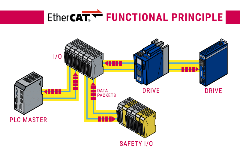
The functional principle of EtherCAT communication shows the movement of data packets from a PLC master to and from I/O blocks, VFDs/Drives, and Safety I/O.
Higher-level protocols such as HTTP use an individual ethernet frame to send data to each device on the network. By using a single ethernet frame that contains data for multiple devices the amount of data overhead on the network is greatly reduced. An additional benefit of transmitting process data at the data link layer is the need for a switch to route data is eliminated. This allows EtherCAT to achieve low cycle times with low jitter.
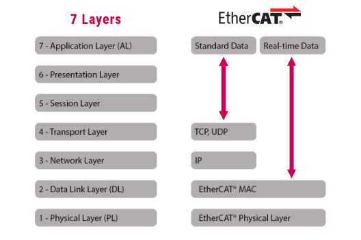
EtherCAT protocol layer block diagram showing standard data and real-time data (Image source).
The distributed clocks feature makes deterministic communication possible with the hardware architecture and frame structure. When distributed clocks are enabled the master uses a reference clock and compares it with the local clock on each slave. The master then calculates the offset between the reference and slave clock and inserts an offset. Since all nodes share the same system time each slave can process data in a synchronized fashion.
Flexible Topology
Wiring flexibility and the maximum number of devices allowed on a given network are important factors when selecting a fieldbus. EtherCAT can be implemented as a centralized or decentralized network. Daisy chain, tree, star, or line topologies is possible without impacting performance. Up to 65,535 devices can be connected up to 100m apart using a centralized or distributed architecture.
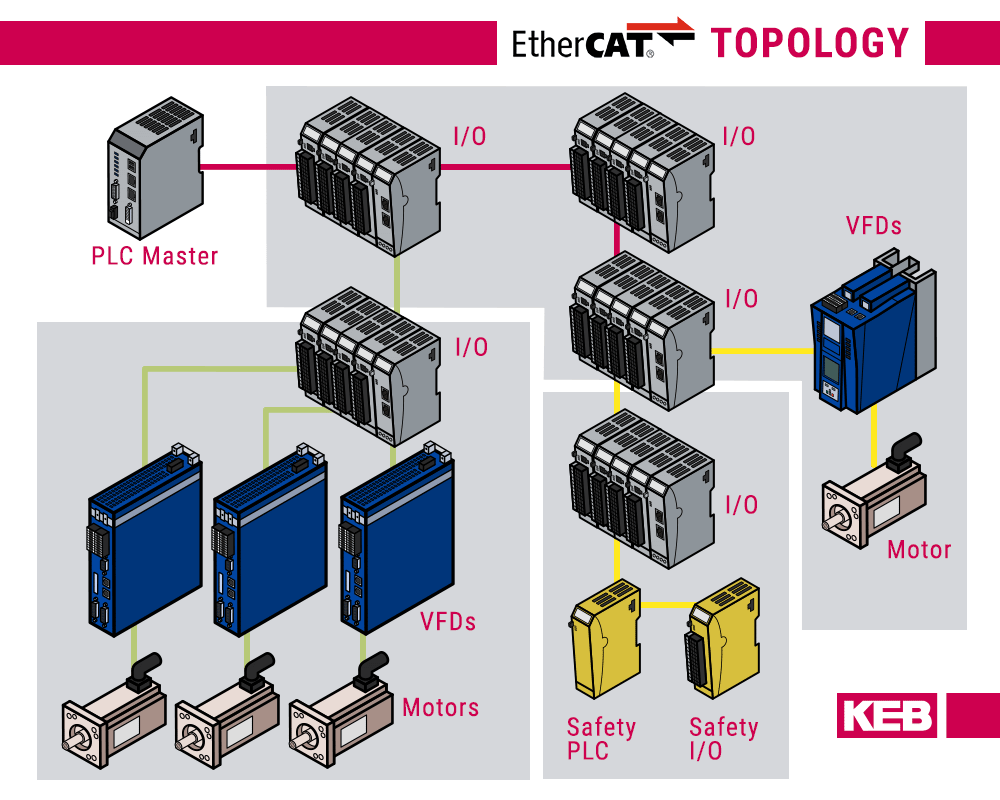
Topology of an EtherCAT system with safe IO, VFDs, and motors connected to a PLC Master.
Communication Profiles and IoT Integration
Ease of use and diagnosis of system errors is possible with the wide variety of communication profiles available with EtherCAT. Application protocols such as CAN application protocol over EtherCAT (COE) reduce development time by providing a standard mapping of communication objects to reduce development time. Slave-specific variables, device file access, and diagnostics are also possible via communication profiles such as Ethernet over EtherCAT (EoE), ADS over EtherCAT(AoE), and file access over EtherCAT.
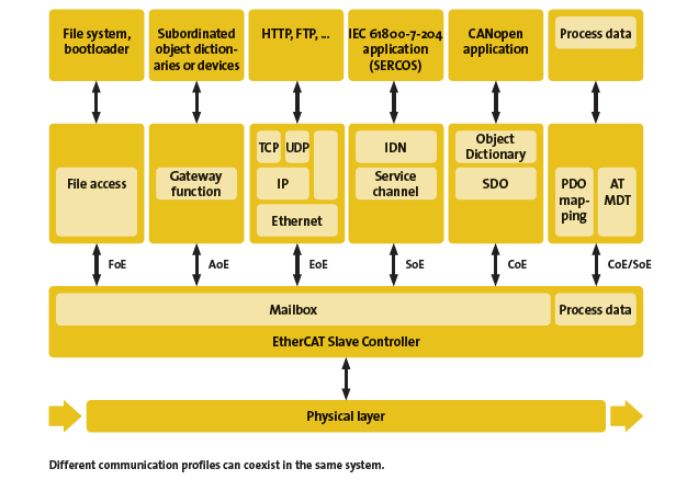
Image from EtherCAT Technology Group
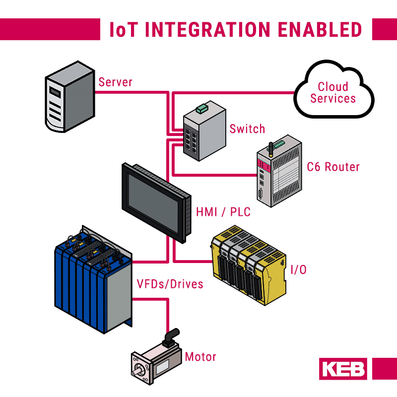
With the emergence and continued development of the Internet of Things (IoT), EtherCAT allows for popular protocols MQTT, AMQP, and OPC UA for communication with cloud-based services and M2M communication. Cloud connectivity can be implemented onboard the controller or from an edge-based gateway on the EtherCAT network.
Safety Integrated
Fail-Safe over EtherCAT allows for the transfer of safety-critical control data over the standard EtherCAT network. Standard communication with safety data in a single channel is known as the black channel. Using the black channel approach safety data is packaged in the standard Ethernet telegram with safety-specific frames to secure the data.
FSoE can be used to replace discrete wiring to save wiring costs, decrease the required panel space and reduce the possibility of wiring errors. FSoE can be used to quickly detect errors and activate safety functions via software. For example, drive-specific functions such as STO, SS1, SS2, SOS, etc. can all be activated over the bus using bits in the safety control word.
Lastly, FSoE is certified to an IEC 61508 SIL3 level and independently certified by TÜV SÜD Rail GmbH ensuring compliance to safety standards making overall implementation and machine certification.
Open Protocol
EtherCAT technology is specified by the EtherCAT Technology Group (ETG). The ETG consists of control vendors, OEMs, and machine builders to ensure protocol interoperability among different vendors. The “open” philosophy ensures users can freely select their preferred vendor without the risk of being tied to one vendor. The ETG also provides configuration tools, documentation, and guidelines for users.
KEB Delivers on EtherCAT
Contact a KEB engineer to learn how EtherCAT will improve your system’s motion control!
The content & opinions in this article are the author’s and do not necessarily represent the views of ManufacturingTomorrow
Comments (0)
This post does not have any comments. Be the first to leave a comment below.
Featured Product
