Three-phase induction AC motors produce mechanical power for almost 80% of industrial applications by providing extremely high efficiency and environmentally rugged characteristics. Effective control of these motors is needed to tackle heavier load problems .
 Use Reliable Isolation ADCs to Effectively Control Three-Phase Induction Motors
Bonnie Baker | Digi-Key Electronics
This control is challenging for designers as the three-phase motor electronics require isolated analog signal feedback across the current shunts from the high voltage, common-mode signals. In addition, the high dynamic isolation voltages must be sustained over a wide ambient temperature range.
The solution to precision three-phase induction AC motor control for many applications lies with current sense circuitry and the isolated analog-to-digital converter (ADC) functions, such as an isolated modulator. This ADC function creates a capture mechanism for the switching power inverter’s high voltage signal across a current shunt resistor for AC motor control applications.
This article discusses the issues associated with achieving precise AC motor control and why isolated analog feedback is a good option for this type of application. It then introduces an isolated sigma-delta modulator from Analog Devices, as well as a sin px/px, or sinc, digital filter for the modulator output signal to create a 16-bit ADC word while taking advantage of its isolation barrier.
Introduction to the three-phase induction AC motor
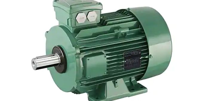
The high-performance servomotor’s primary characteristics are to have a smooth rotation down to a stall, full control of torque at stall, and fast decelerations and accelerations. High-performance motor drive systems usually use three-phase AC motors (Figure 1). These machines replace the DC motor as the machine of choice because of their low inertia, high output-power-to-weight ratios, robust construction, and good rotational high-speed performance.

Figure 1: Industrial three-phase induction AC motor with the output rotating shaft on the left and the electrical terminal box on top. (Image source: Leroy-Somer)
The principles of vector control, also called field-oriented control, manage these AC motors. Most modern high-performance drives have digitally implemented closed-loop current control. In this system, the achievable closed-loop bandwidth depends on the execution rate of the computationally intensive vector control algorithms and the real-time implementation of associated vector rotations. This computational burden requires digital signal processors (DSPs) to implement a sinc digital filter and the embedded motor and vector control schemes. The computational power of the DSP permits fast cycle times and closed-loop current control bandwidths.
The complete current control scheme for these machines also requires a pulse-width modulation (PWM) high voltage generation scheme and a high resolution ADC for measurement of the motor currents. The smooth control of torque to zero speed, rotor position feedback maintenance is essential for modern vector controllers. Here, we describe the fundamental principles behind implementing a high-performance ADC for three-phase AC motors—combining a 16-bit isolated analog-to-digital modulator and an integrated DSP controller with a powerful DSP core and flexible digital sinc filter generation.
Isolation strategy
High-performance three-phase AC motors need a smooth rotation down to stall, full control of torque at stall, and fast accelerations and decelerations. The measurement of the motor's speed with transducers, and the torque with phase currents, control isolated gate drivers directly (Figure 2).
")
Figure 2: This three-phase motor driver system (U, V, and W) has FET inverter transistors to drive the motor, and current measurement resistors, RS, to sense the current magnitudes. (Image source: Analog Devices)
The sense resistors, RS, in Figure 2 capture the motor’s winding current. A 16-bit conversion uses these signals to dynamically measure the motor’s torque. The Hall effect sensor captures the motor’s position. This system captures both the torque and position over time.
There are significant voltage reference issues to understand when powering a three-phase motor control system. Isolation is a crucial challenge with the inverter stage on the power board and the processor on the controller board. The ground references for these two boards differ, requiring isolation products to protect the devices and users from potential damage and harm.
A three-phase AC motor common-mode gate driver voltage can be as high as 600 volts or more, with the pulse-width modulation (PWM) switching greater than 20 kilohertz (kHz) and rise times of 25 volts per nanosecond (ns) for IGBT inverters. These voltage and rise time characteristics require isolation devices to protect sensitive circuitry in this hostile environment. Sensing of the currents to the motor is essential with minimal system interference. The sensor of choice for the three-phase motor is an extremely small sense resistor (RS). The isolated system also improves noise immunity in the motor control system.
Isolated systems cater to two major areas of design concern: extremely high bridge common-mode voltages and the capture of the motor currents (IU, IV, and IW). In Figure 3, Analog Devices’ ADuM7701 sigma-delta isolated ±250 millivolt (mV) input modulator provides the digital signal from the secondary side to the primary side.

Figure 3: This three-phase AC motor circuit uses the ADuM7701 magnetic isolated sigma-delta modulator to capture the motor current magnitudes and the ADSP-CM408F DSP to implement sinc filters and evaluate the motor’s condition. (Image source: Analog Devices)
Its operating temperature is from -40°C to 125°C, with a high common-mode transient immunity of 10 kilovolts (kV) per microsecond (ms) across the isolation barrier. The ADuM7701 isolated side power is 4.5 to 5.5 volts, while the ADSP-CM408F DSP chip operates at 3.3 volts. This system overcomes the difficulty of isolating the analog switching power inverter’s high voltage common signal that appears across the current shunt resistors (RS).
The determination of the IV and IW shunt resistor (RS) values in Figure 3 depends on the specific voltage, current, and power application requirements. Small resistors minimize power dissipation but may not utilize the full ADuM7701 input range. Higher value resistors achieve maximum signal-to-noise ratio (SNR) performance by using the full ADC performance input range. The final values chosen are a compromise between accuracy and low power dissipation.
The specified maximum input voltage of the ADuM7701 modulator is ±250 mV. RS must be less than VMOD_PEAK/ICC_PEAK to satisfy these constraints. For the example in Figure 3, if the power stage peak current rating is 8.5 amperes (A), the maximum shunt resistance is 29.4 milliohms (mΩ).
Sigma-delta modulator operation
The front end of the ADuM7701 is a second-order modulator with an input common-mode range of -0.2 volts to +0.8 volts. The second-order, sigma-delta modulator circuitry contains two analog sigma (integrator) stages with two analog delta (subtractor) stages. The output of this combination is compared to a reference voltage, such as ground, to clock a one-bit digital output (Figure 4).

Figure 4: The front end of the ADuM7701 comprises a second-order sigma-delta modulator that combines two analog sigma (integrator) stages with two analog delta (subtractor) stages. (Image source: Analog Devices)
The clocked 1-bit stream is presented to a digital/decimator filter, as well as being fed back to a digital-to-analog converter and then to the analog subtractor stages. To achieve the best overall ADC performance, the signal combines with the ADSP-CM408F to create a sinc filter that converts the modulator signal to a fully operational 16-bit word. The immediacy of the modulator’s 1-bit code provides instant overrange conditions. The complete system converts the resistive sensed motor leg currents to provide the appropriate motor torque information.
Digital filter
The output of the ADuM7701 modulator connects to the ADSP-CM408F digital filter’s primary, secondary, and clock inputs. The primary signal path proceeds to the sinc/decimation filter module. The secondary signal path has overrange comparators to quickly detect a system fault condition.
The frequency of the modulator—5 megahertz (MHz) to 21 MHz clock (fM)—and the decimation rate (D) define the sinc filter performance. The sinc filter order (O) is one order higher than the modulator. Therefore, with the ADuM7701 the sinc filter is third order. Equation 1 shows the filter frequency response.
 = [1/D x sin(D πf/fM)/sin(πf/fM) x e -j(D - 1) πf/fM]O")
Equation 1
Matching the decimation frequency to the motor PWM switching frequency significantly reduces PWM switching harmonics. The frequency response in Figure 5 has zeroes at frequencies that are even multiples of the decimation frequency (fM/D).

Figure 5: 3rd-order sinc digital filter amplitude response. (Image source: Analog Devices)
Conclusion
High-performance three-phase AC motors require smooth rotation down to a stall, full control of torque at stall, and fast decelerations and accelerations. Accomplishing this motor control task requires real-time measurements of the motor’s torque, position, and fault conditions. The designer’s challenge is to understand the AC motor precision requirements, select an isolation strategy, choose an appropriate sigma-delta path, and implement a sinc digital filter.
Using an isolated modulator and a mixed-signal control processor such as the ADuM7701 and the ADSP-CM408 from Analog Devices, designers can create a high-precision, robust motor control system for water pumps, boiler pumps, grinding machines, and compressors.
The content & opinions in this article are the author’s and do not necessarily represent the views of ManufacturingTomorrow
Featured Product