By following mounting best practices, designers can be sure that their feedback loop is providing accurate data that will enable the system to meet topline performance levels.
 Best Practices for Encoder Mounting
London Rhodes, Application Engineer | Dynapar
Encoders are sensors used to optimize speed and position performance of a motion-control system by providing feedback on the driven shaft. Feedback is only as good as the quality of the data, however, which can be compromised by spatial, environmental, and mechanical factors. By following mounting best practices, designers can be sure that their feedback loop is providing accurate data that will enable the system to meet topline performance levels.
An optical rotary encoder consists of a patterned code disc that turns with the load and a source-detector pair that is fixed to the frame of the machine. The source is mounted on one side of the disc and the detector is mounted directly opposite. As the disc turns, it modulates the optical beam; the resultant signal can be processed to yield speed and/or position data. Magnetic rotary encoders operate analogously, using a code wheel with alternating magnetic domains as the modulating device.
Rotary encoders can be divided into four types:
- Shafted
- Hollow-shaft
- Hub-shaft
- Bearingless
The optimal mounting approach depends upon the encoder type, the application, and the mechanical design of the machine. The code disc/code wheel of the detector needs to be attached to the shaft being tracked, while the source-detector portion needs to be tethered or fixed to the frame of the equipment.
Mounting Shafted Encoders with Couplings
For proper mounting, a shafted encoder requires two special interfaces: an encoder mount and a connection from the encoder shaft to the motor shaft or load. The encoder mount is usually either a mounting flange or a foot mount that is used to attach the encoder to a fixed surface, typically a bracket or adapter.
.jpg)
Figure 1: An encoder mount can be either a mounting flange (left) or a foot mount (right).
The connection to the driven shaft is typically made using either a flexible coupling or a belt drive. The flexible coupling connects the encoder shaft directly to the motor or driven shaft using set screws. It isolates the encoder from shock and vibration, and movement in the motor shaft.
Mounting an encoder through a flexible coupling has several advantages. The approach isolates the encoder from noise generated by high currents supplied to and generated by the motor. Electrical noise can cause the encoder to miss pulses or introduce spurious pulses.
Flexible couplings provide mechanical benefits. Flexible couplings can absorb shaft movement and compensate for shaft misalignments, which can allow for installations on older motors or motors that are used in high shock and vibration applications.
As always, there are trade-offs. Coupling an encoder can add up to seven inches in line with the motor shaft when you consider the bracket, the shaft gap within the coupling, and the encoder housing. Connecting shafts with the coupling requires careful alignment of encoder and driven shafts to avoid damage to the coupling. As a result, the approach increases installation time and complexity. Hollow-shaft and hub-shaft encoders provide an alternative option without the need for a coupling.
Direct Mounting with Hollow-Shaft and Hub-Shaft Encoders
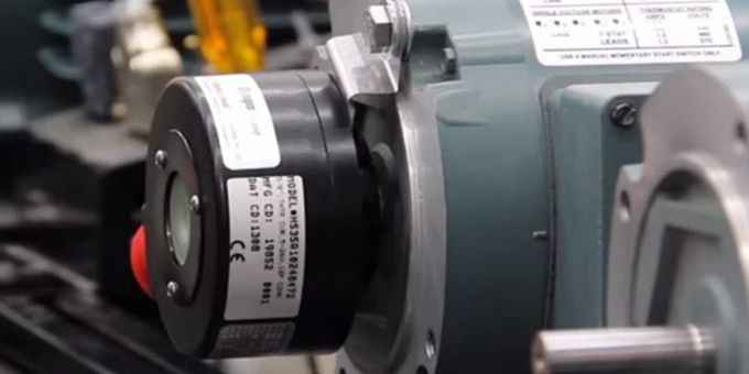
Hollow-shaft encoders have hollow bores that enable them to be directly mounted on the shaft of the motor and affixed using a concentric clamp. In this mounting configuration, a flexible tether or torque arm attaches to the motor face or any fixed object to prevent the encoder body from rotating with the shaft (see figure 2). Internal bearings enable the code disc to turn with the driven shaft.
.jpg)
Figure 2: A hollow-shaft encoder can be directly mounted on the motor or driven shaft.
Direct mounting is also effective for hub-shaft encoders. This mounted method is similar to hollow-shaft but the encoder caps over the end on the shaft. The shaft does not penetrate through the encoder.
With direct mounting, it is important to isolate the encoder from motor shaft current. This is accomplished using a plastic sleeve or insert between the motor and encoder shafts. If an insert is not available, the encoder will have to rely on the motor for a shaft-current solution or on another shaft grounding kit accessory. If not properly grounded, motor shaft currents will travel through the encoder’s bearings and potentially damage them.
Direct mounting offers several advantages. It is usually easier to select the appropriate encoder for the motor by matching the shaft size of the motor to the hollow- or hub-shaft encoder bore (or shaft) size. Installation is also simpler as direct mounting eliminates the need for a coupling, does not require motor shaft alignment with respect to the encoder, and allows for mounting at various radii from the center of the motor shaft through the use of slotted tethers. Encoder inserts and spring tethers also help make direct mounting more robust than coupling mounting: They isolate encoders from motor shaft current and help absorb sudden shaft movements, both of which can extend the life of the encoder bearings.
Direct mounting does require improved sealing as there is a larger area of the encoder in contact with the driven shaft, increasing the exposure of the encoder electronics. A hub-shaft encoder with require a more precise shaft length to properly locate the encoder for tethering, but provides better sealing, as there is no opening on the back of the encoder.
Ring or C-Face Mounting with Bearingless Encoders
Ring or C-Face mounting is the best choice for bearingless encoders. A bearingless encoder is a modular design that consists of the encoder housing, one or multiple sensor modules, and a magnetic code wheel. The housing of the encoder mounts to the motor face on the drive or accessory end of the motor, using pilot dimensions that comply with NEMA or IEC standards. The wheel is inserted onto the motor shaft, aligned to the sensor embedded within the housing, and fastened into place (see figure 3).
.png)
Figure 3: A bearingless encoder is a modular feedback device with different components that mount to the motor face and to the motor shaft.
This design approach is good for applications requiring long lifetime and high reliability. The absence of any mechanical connection between the wheel and the sensor eliminates potential failure points and allows sensors to have potted electronics. This is an improvement over direct mount encoders that rely on the integrity of a series of connector and shaft gaskets. Since there are no encoder bearings, motor shaft currents do not affect the encoder’s operation or lifetime.
Another benefit of ring mounting is that the encoder leverages the motor bearing, removing a critical failure point from the system. Finally, bearingless encoders mount directly to the face of the motor, reducing the space required as well as the amount of the motor’s shaft consumed by the encoder.
In Summary
When it comes to encoder mounting configuration, there is no one perfect solution, of course, only the best solution for a given project or application. Coupling, direct, and ring mounting are the primary mounting options available for closed-loop feedback applications. They will all have their place according to the environment they are installed in, the age of the motor it will be installed on, and the mounting provisions that exist in the application.
About London Rhodes
London is a former Avionics Technician for the USMC. He has over 15 years of experience in Electronics and 10 years of experience in motion feedback applications. In his role as application engineer for Dynapar, London provides technical advice in the selection, use and troubleshooting of encoders and resolvers. He spends his free time with his family, gadgets and motorcycles.
The content & opinions in this article are the author’s and do not necessarily represent the views of ManufacturingTomorrow
Featured Product