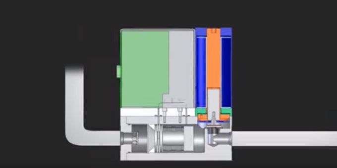
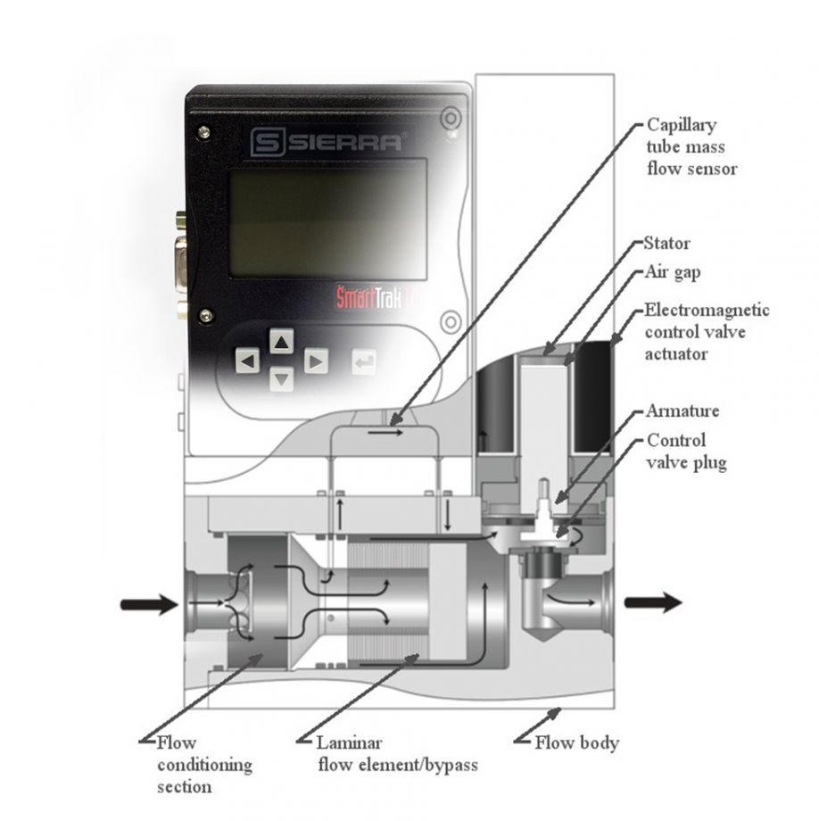
A mass flow meter (MFM) has five major components: flow body, flow conditioning section, flow sensor tube, bypass, and electronics. A mass flow controller (MFC) has the same components as an MFM, but also has an integral control valve mounted on the same flow body as the MFM
 Major Components of Mass Flow Meters and Controllers

Matthew Olin, President | Sierra Instruments
Have you ever wanted to look inside a mass flow meter or controller to understand the mechanical components? This blog, as part of our ongoing core technology series based on excerpts from Sierra’s Founder and Chairman, Dr. John G. Olin’s, white paper entitled, “Capillary Tube Thermal Mass Flow Meters & Controllers – A User’s Guide,” dives “under the hood” and takes a closer look at the flow body, flow rates & sizing, and how flow conditioning works.
Under the hood – The Major Components of a MFM & MFC
A mass flow meter (MFM) has five major components: flow body, flow conditioning section, flow sensor tube, bypass, and electronics. A mass flow controller (MFC) has the same components as an MFM, but also has an integral control valve mounted on the same flow body as the MFM (See Figure 1).

Figure 1.
The Flow Body
General purpose mass gas flow meters and mass flow controllers (MFC) typically have only three flow body sizes covering the entire flow range of the instruments: low flow, medium flow, and high flow. The gas flow ranges of the three flow body sizes are shown in in the table below. Low flow bodies often are machined out of a single piece of stainless steel bar stock. To get an idea of their relatively compact size, MFCs have the following approximate widths and lengths (not including inlet and outlet fittings): low flow—1.0 W x 3.0 L inches (25 W x 76 L mm); medium flow—1.5 W x 4.5 L inches (38 W x 114 L mm); and high flow—3.0 W x 9.0 L inches (76 W x 229 L mm). MFMs usually have the same widths but have about two-thirds the length in the medium and high flow sizes.
| Flow Body Size | Maximum Mass Flow Rate Range (slpm) |
| Low Flow | 0 to 50 |
| Medium Flow | 0 to 300 |
| High Flow | 0 to 1500 |
The flow body has inlet and outlet flow conduit fittings and houses the flow conditioning section, the flow sensor tube, the bypass/laminar flow element, and, in the case of MFCs, the control valve. The electronics are mounted in their enclosure on the top of the flow body. The wetted parts of a typical flow body and its internal components are made of corrosion resistant materials. Typical wetted materials for the flow bodies of general purpose MFMs and MFCs are: 316 L stainless steel; ferromagnetic stainless steel in the valve; and “O” rings and valve seats of fluoroelastomers and other advanced elastomeric materials. Some lower cost instruments intended for light duty and lower accuracy applications have flow bodies made of plastic or aluminum.
Instruments with elastomeric seals throughout the flow body have relatively low rates of leakage in and out of the flow body. MFMs and MFCs used in vacuum processes use metal seals at all locations in the flow body to further reduce leak rates. Manufacturers should subject every instrument to a helium leak check using a mass spectrometer leak detector, or equivalent instrument. Additionally, all instruments should comply with applicable pressurized equipment standards and codes, and manufacturers should pressure test all instruments to insure compliance.
Process lines typically are tubes with outside diameters of 1/8, 1/4, 3/8, 1/2, 3/4, and 1 inch (6, 10, 12, and 20 mm). The 1/4 inch (6 mm) tubing size is most common. Some MFMs operated at very high flow rates are available in wafer and flange pipe sizes. Manufacturers offer a broad selection of process tube fittings, including: compression fittings, elastomeric “O”-ring face seal fittings, and metal gasket face seal fittings. Since the inlet and outlet fittings contribute to the pressure drop in the instruments, the size of the fittings should be as large as practicable within constraints imposed by the size of the process line.
Semiconductor MFCs
Semiconductor MFCs often have a particulate filter, pressure regulator, and a positive shut-off valve installed upstream of the instrument and may have a positive shut-off valve and pressure regulator installed downstream. General purpose instruments also may include ancillary flow components in their installation.
Semiconductor MFCs used in the fabrication of high-end semiconductor devices have several special requirements to ensure that: (1) no particulates or other contaminants enter the fabrication process; (2) no toxic process gases escape the MFC; and (3) no ambient air enters the process. Typical specifications are: wetted surfaces must have high purity and be highly polished (surface roughness in the range of about 4 to 10 microinches Ra (0.1 to 0.25 micrometers Ra); leak rates must be extremely low; and internal flow paths, as shown in Fig. 3 (no figure 3 shown here), must have no sharp corners, cavities, or dead spaces where particles can form. Semiconductor MFCs are available in both in-line and down- port configurations. Down-port versions reduce the axial dimensions of the MFC and its ancillary flow components, thereby facilitating the compactness required by manufacturers of semiconductor equipment.
The Flow Conditioning Section of an MFM & MFC
The flow entering the MFM or MFC may have non-uniformities in its flow profile due to upstream disturbances caused by elbows, contractions, expansions, and the inlet fitting. This is particularly true for mass flow rates greater than about 50 slpm in the medium and high flow sizes. The flow conditioning section shown in the image above eliminates these upstream flow non-uniformities and conditions the flow so the sensor tube and bypass are able to create the necessary laminar flow in their passages. Downstream flow non-uniformities have no effect on instrument performance.
In operation, the jet issuing from the inlet fitting in enters the flow conditioning section and impacts a central plate. It then flows radially outward and strikes the cylindrical inner wall of a settling chamber. This tortuous flow pattern effectively erases any non-uniform past history of the flow. A settling chamber then slows down the flow and allows viscous forces to reduce non-uniformities. The flow profile then becomes uniformed and flattened as the stream lines encounter a flow resistance as they pass through the inlet filter plate or screen that also captures any remaining particulate contaminants. After the inlet filter, the flow profile is further flattened as it passes through a flow nozzle. At this point, the uniformed flow splits into the two paths described earlier: one to the sensor tube and the other to the laminar flow element/bypass.
Low flow instruments with mass flow rates less than about 50 slpm, such as semiconductor MFCs, do not require a flow conditioning section. Because of this and the use of flow conditioners for higher flow rates, capillary tube thermal MFMs and MFCs of all sizes do not require straight lengths of upstream and downstream piping (i.e., tubing) that are required by most other kinds of flow meters.
To see how the flow conditioning section works, watch our video “How Capillary Thermal Mass Flow Controller Technology Works.”
The content & opinions in this article are the author’s and do not necessarily represent the views of ManufacturingTomorrow
Comments (0)
This post does not have any comments. Be the first to leave a comment below.
Featured Product

