The customer required precision rotary axis control in the lowest profile form factor for multiple sequential robot arm joints. Key additional requirements included minimal movement at start-up to report absolute position...
Celera Motion Case Study – Precision Rotary Axis Control
Contributed by | Celera Motion
The Challenge
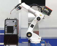 The customer required precision rotary axis control in the lowest profile form factor for multiple sequential robot arm joints. Key additional requirements included minimal movement at start-up to report absolute position, and minimal signal cabling keep the overall arm size as small as possible.
The Solution
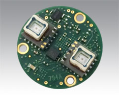 A series of custom-sized PCB-based encoder modules with FPGA control and BiSS communication interfaces was developed by MicroE, each featuring two standard ChipEncoder™ readheads and a Micro Motion Absolute™ (MMA) rotary grating disk. MMA grating technology employs a standard 40 micron pitch incremental counting track, coupled with a reference track where each index is uniquely spaced. With only a small movement at start-up, multiple index marks are detected, and the measured spacing is compared to a lookup table in firmware to determine the absolute position.
The Benefit
 The output of the two encoders are averaged for improved rotational accuracy, and absolute position is determined at start-up with minimal axial rotation. BiSS serial communication protocol allows each successive robot joint to be connected in a daisy-chain arrangement, rather than having dedicated bus cables for each axis, which along with the small size of the ChipEncoder helps reduce the overall size of the each joint. High speed serial communication (32MHz clock, 1µsec update rate) assures high robot responsiveness to the operator’s commands.
Specifications
| PCB Diameter | 20mm |
| Scale Diameter | 15mm |
| Total Module Height | 13.8mm |
| Serial Interface | BiSS C |
| Clock Rate | 32 MHz |
| Position Update Rate | 1µsec |
| Resolution | 85,280 CPR (15.2 arc-sec; 73.7µrad) |
| Cable Wire Count | 5 twisted pairs, 32AWG |
The content & opinions in this article are the author’s and do not necessarily represent the views of ManufacturingTomorrow
Comments (0)
This post does not have any comments. Be the first to leave a comment below.
Featured Product

T.J. Davies' Retention Knobs
Our retention knobs are manufactured above international standards or to machine builder specifications. Retention knobs are manufactured utilizing AMS-6274/AISI-8620 alloy steel drawn in the United States. Threads are single-pointed on our lathes while manufacturing all other retention knob features to ensure high concentricity. Our process ensures that our threads are balanced (lead in/lead out at 180 degrees.) Each retention knob is carburized (hardened) to 58-62HRC, and case depth is .020-.030. Core hardness 40HRC. Each retention knob is coated utilizing a hot black oxide coating to military specifications. Our retention knobs are 100% covered in black oxide to prevent rust. All retention knob surfaces (not just mating surfaces) have a precision finish of 32 RMA micro or better: ISO grade 6N. Each retention knob is magnetic particle tested and tested at 2.5 times the pulling force of the drawbar. Certifications are maintained for each step in the manufacturing process for traceability.
