Companies who do not carry out emulation (or virtual commissioning) can only start controls testing when the real system is at least predominantly assembled, which means they are near ramp and handover, with a large amount of unpredictable testing yet to be started, and probably onsite and under close client scrutiny. Hardly the best of conditions for carrying out the methodical task of analytical verification, debugging and repair.
Industrial Software for Simulation and Emulation
Ian McGregor | Emulate3D
Tell us about Emulate3D, what you do and how it all got started
Emulate3D develops engineering software designed for use in industrial automation projects where complex material handling is required. Typical applications include fulfilment centres, warehouses, automated manufacturing facilities, and airport baggage handling systems.
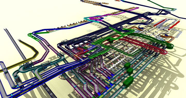
Gatwick Airport North Terminal Sim3D exploratory flow model (image courtesy of AutoLogic Systems)
Most users are industrial or design engineers, consultants, and controls engineers. Apart from developing and publishing the range of software products, Emulate3D trains and supports users across the Americas, as well as supporting a network of worldwide distributors. The company was founded in 2005 because we identified a gap in the market – existing industrial simulation products were not providing a good solution for virtual controls testing, and we could see how to do that, and how to grow the market. Emulate3D was the first company to incorporate physics-based movement into industrial material handling models, which meant we had a realistic and straightforward solution for both controls testing and believable product movement. This approach was vindicated by the ongoing success of the products and by a Queen’s Award for Innovation in 2014.
Emulate3D develops industrial software for simulation and emulation - what's the difference?
Both types of model are event driven – which means that loads or products introduced into a model trigger logic when they get to certain places within the system (such as photo eyes or sensors) and the model is dynamically changed as a result (by a motor being switched on or off, for example). The essential difference is in the controls, or operational logic – a simulation model has all its logic detailed internally, whereas an emulation model is controlled by an external control system.
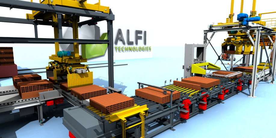
Brick Palletising System Demo3D model (image courtesy of ALFI Technologies)
The emulation model is designed to be connected to a real control system, so the model becomes a reliable and accurate replacement for the real material handling system, such that the controls can be logically tested and debugged. Simulation models are often less detailed, as the objective is to create a useful way of testing the overall business logic of a system and creating series of experiments to help with the overall understanding of the system response. This fundamental difference means that emulation models cannot run faster than real time if they are connected to a control system containing timers, whereas simulation models are often only useful if they can run many times faster than real time.
How does a company get value out of investing in emulation software?
Companies who do not carry out emulation (or virtual commissioning) can only start controls testing when the real system is at least predominantly assembled, which means they are near ramp and handover, with a large amount of unpredictable testing yet to be started, and probably onsite and under close client scrutiny. Hardly the best of conditions for carrying out the methodical task of analytical verification, debugging and repair. Emulation takes the logical testing process off the project’s critical path, enables testing to begin as soon as the system design is finalised, and to be carried out in parallel to the system build. Computer-based testing is more easily repeatable, safer, and cheaper to run than onsite testing where existing production may further complicate the situation. Operators can also be trained safely in normal operation, error recovery, and start up using the actual HMI screens connected to the control system and without compromising the existing facility. Emulation reduces the amount of time PLC engineers spend on site both before and after handover, and the fact that more complete testing can be undergone as the debugging can begin earlier in the project cycle, and results in more robust control systems.
Where do your clients get benefits from using simulation software?
Simulation models provide a shared focus for all project stakeholders – they represent the current state of the decision-making process during the development stage, and serve as a unique and clear means of understanding the operation of the system under various conditions. The apparent complexity in automation systems arises from simultaneous events which are difficult to imagine and understand without the help of a recognisable model. Not only can the model be replayed at any speed, but it also serves as a responsive testbed for comparing layout alternatives and demonstrating numerically the reasons why one solution is better than another.
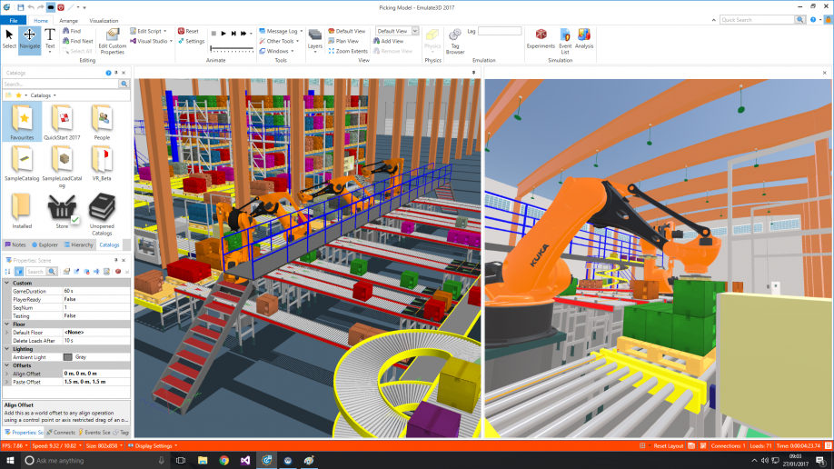
Demo3D edit environment showing Virtual Reality headset view on the right hand side of the image.
As alternatives are tested and choices made, the statistics generated by a simulation model build a level of confidence in the outcome and reduce the risk associated with the investment.
Give us an idea of the process involved in using Emulate3D products - and how hard is it?
Emulate3D products were designed from the start for a wide range of user profiles – from occasional project-based use all the way through to professional developers responsible for building Emulate3D technology into the heart of their company infrastructure. New users benefit from the straightforward drag and drop construction process known as Quickstart, where working models can be put together in minutes from the supplied catalogs of commonly-encountered material handling elements such as conveyors, AS/RS, fork lift trucks, robots, and operators. Routing logic can be modified within certain control elements, and extended using the FlowControl drag and drop logic editor. Users wishing to add more graphical detail such as machines, buildings, floorplans or products can import CAD from a wide range of industry-standard CAD products and formats such as SOLIDWORKS, Inventor, SketchUp, RealDWG, VRML, and many others. These elements can be purely visual, or can be transformed into operational elements with built-in logic to be saved in user catalogs for reuse in other models. Emulate3D provides a fully integrated Microsoft Visual Studio editing and debugging environment for power users who wish to add components, control elements, and further customisations and integrations using C#. Online training is available for all levels of users, and there is extensive online self-support in the form of a knowledgebase, a user forum and tutorials and examples, as well as guided support through email and web meetings.
Look down the road a few years; where do you see Emulate3D and future developments in simulation and emulation?
Emulate3D is a powerful and robust simulation, demonstration, and emulation environment with a growing, enthusiastic, and productive user base. In the thirteen years of its existence to date the company has never been short of development ideas and opportunities to improve and extend the products, and that remains true today. These ideas come from experience within the company but also from within our user base – the accumulated knowledge that comes from making and deploying automation systems around the world is an invaluable resource, and we learn so much from listening to the experiences and thoughts of those industry experts who are generous enough to share them with us for the benefit of all. Over the last few years we chose to make certain product developments which positioned us to benefit from the rise in virtual and augmented reality, and we’ve seen considerable proof that these technologies are transforming the way companies deploy simulation and emulation models across their different sites. Colleagues who previously flew around the world for brief project meetings to discuss system details can now meet at a moment’s notice within the same model, move around together in it, and experience the changes in a way that is convincing and effective. More convenient, easier to set up, less expensive and with little to no greenhouse gases generated, virtual presentations are understandably very popular with our users. Both virtual and augmented reality are still in their early stages of development, with much more to come. We can already interact with models within the virtual environment – virtual machines controlled by real PLCs and higher-level control systems can be started and stopped using a browser-based HMI; loads can be removed from conveyors and placed elsewhere, discarded or piled up to test the control system response; buttons can be pressed and levers pushed and pulled. We even have a convincing pick-to-light model that regularly stimulates competition between colleagues at trade shows!

About Emulate3D
Emulate3D develops cost-effective software products that facilitate the demonstration, understanding, and sale of Automated Material Handling Systems, and their efficient market deployment, support and maintenance.
The content & opinions in this article are the author’s and do not necessarily represent the views of ManufacturingTomorrow
Comments (0)
This post does not have any comments. Be the first to leave a comment below.
Featured Product