Rather than sizing up to a slide model with very large diameter guideshafts, you may be able to use a smaller model with the addition of the optional center support.
Selecting Pneumatic Linear Slides for Automated Assembly Equipment
Contributed by | Fabco-Air
A pneumatic linear slide combines an air cylinder power source with a guide mechanism that supports the workload over a precise linear path. They can perform tasks as simple as a pressing operation, or as demanding as multi-axis robotics.
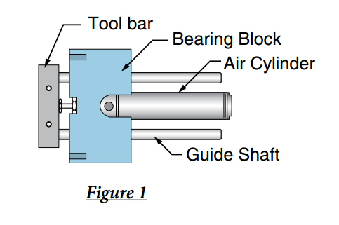
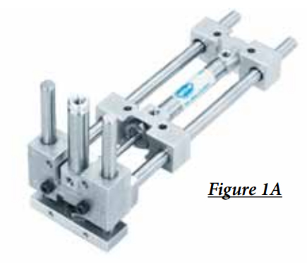
Figure 1 shows the top view of one style of linear slide that could be used in a pressing application. The guide mechanism consists of a bearing block with two guide shafts attached to a common tool bar. Below, two linear slides have been combined to form a two axis slide. Figure 1A.
Today’s equipment designer can choose from a wide array of Linear Slide models offered in the marketplace, but how does one decide which model best suits the application?
Slide Selection
Selecting a linear slide involves several basic factors, including:
- What Force is required - determines air cylinder bore size
- Load capacity required - determines size and bearing type of the slide guide mechanism
- Stroke required - total linear distance traveled
- Operating speed - cycles per minute and/or inches per second
By utilizing the slide manufacturer’s Engineering Data provided for each model series, much engineering time can be saved. Data in this article will be expressed in US Customary units of pounds and inches.
Force
By using the formula Force = PSI x Area (power factor), the linear slide’s cylinder bore is determined. Note that many slide models have a different power factor for the extend and retract stroke (factor considers area lost by the piston rod). If the application involves pressing, such as an assembly operation, consider the possibility that more force may eventually be required than initially expected. A preventative solution is to size to a larger bore and regulating it to a lower supply pressure. This pressure can then be increased when required, to increase the slide’s output force. Another method of increasing slide’s output without sizing to a model with a larger bore is to utilize a tandem cylinder or Multi-Power® option. (Multi-Power® is a registered trademark of Fabco-Air, Inc.)
Lifting applications require that the slide have at least twice the output force as the weight to be lifted. Underpowered slides that “just barely lift” the load will operate poorly, with a slow, jerky, and un-controlled motion.
Finally, many applications require very little force, and bore size is often mistakenly ignored. Select a slide with a bore size that provides a sufficient volume of air to operate with a smooth, controlled motion. Avoid excessively large bores that waste air needlessly, and thereby waste energy.
Load Capacity
A slide must support a workload over the length of the linear motion within the limits of precision required by the application. A linear slide carrying a paddle that knocks boxes off of a conveyor does not need the same degree of precision as a parts placer on an Assembly Machine. Because of these wide variances in application requirements, the engineering data pertaining to the slide’s load capacity will indicate safe loading in pounds and predict the amount of toolbar deflection, or bending, in thousandths of an inch.
The largest category of linear slides common today employ two or more shafts as the guiding mechanism. Most workloads are attached to the reciprocating toolbar, producing an overhung load. The load capacity is ultimately determined by two factors - the strength of the guideshaft to resist deflection, and the ability of the linear bearing to support that load. Although overhung workloads produce undesirable loading to the leading edge of the linear bearing, most bearings have a much higher load rating than the strength of the guideshafts (to resist deflection).
Note that a slide with linear ball bearings may be rated for 20 pounds with .005” deflection in an overhung load situation, and yet the four bearings may have a combined load rating of several hundred pounds. This bearing “over-capacity” assures precision and long life even in overhung loading situations.
Linear bearings, whether ball bearings or sleeve type bearings, will support the highest loads when that load is applied over the entire length of the bearing(s). This is commonly known as a carriage load. Two styles of carriage loads are show here. Figure 2A shows a load attached to a mounting plate on the reciprocating slide.
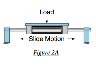
Figure 2B shows a stationary slide with a load plate attached to reciprocating guide shafts.
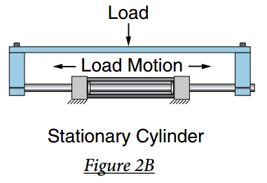
Heavy loads, such as shuttling a toggle press or a rivet unit between two work locations, would best be handled with a linear slide configured as a carriage. Note that a carriage load slide with a short stroke can carry several hundred pounds of workload.
Another element factored into a linear slide’s load capacity is the bore and stroke. Obviously, a linear slide with a load capacity of 200 pounds would be of no use if it were powered by a 1/2" bore cylinder that produced only 10 or 15 pounds of thrust. By the same token, a 30" stroke slide with small 1/4" diameter guideshafts would not have sufficient strength to be of any practical value. Pre-Engineered linear slide packages take into account the need to balance out load capacity versus force available.
Stroke
Slides are commonly offered in 1.0" stroke increments. Designers generally will specify a stroke slightly longer than the application requires, and utilize optional adjustable stops. These hard stops will repeat within +/- .001" stopping accuracy.
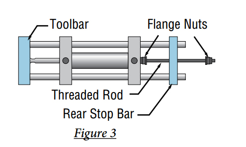
Stop options may consist of clamp collars or a threaded stop bolt / stop nut arrangement shown here in Figure 3.
Linear slide operating speed
An often overlooked aspect is speed. It can be difficult to obtain accurate speed information, yet ignoring speed factors can have disastrous results. A safe speed range for a pneumatic linear slide without external stops is generally 6 to 8 inches per second. A 12" stroke in 2 seconds is approximately 6" per second. It is approximate speed because acceleration and deceleration time has not been taken into account. On shorter strokes, ignoring acceleration/deceleration can be very misleading. A 1.0" stroke in 0.16 seconds is an average speed of 6" per second, but in reality, final speed is much higher because a good portion of time was spent accelerating. High speeds develop severe impact forces when stopped suddenly at end of stroke. Urethane bumpers, either within the cylinder or external, can be used to cushion these forces if stopping accuracy is not an issue. Adjustable stops in conjunction with either hydraulic shock absorbers or optional internal cylinder air cushions can be employed to provide a cushioned, precision stop.
Bearing type and speed are also related. High speeds are best accomplished with linear ball bearings, which can travel up to 100" per second. Short stroke, fast-reciprocating motions should avoid ball bearings. The inertia of the ball circuit tends to make the balls “skid” in their tracks when direction is reversed suddenly.
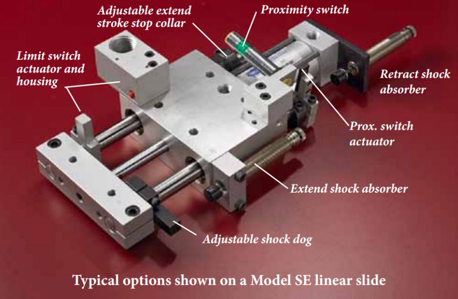
Options
Options allow the designer to custom tailor the linear slide to suit the application. These include toolbar and toolplate styles, bearing type, adjustable stops, shock pads, air cushions or hydraulic shock absorbers, and importantly, sensor options.
Sensors are the interface between the linear slide and the electronic controller. Sensing options are many, and include reed or Hall Effect switches actuated by a magnetic piston band on the slide’s air cylinder. Many slide models offer a proximity switch option operated by a moving “target” on the slide’s motion. Mechanical snap action switches and air pilot switches, as well as LVDT linear transducers may also be available.
Saves time and money
Packaged pneumatic linear slides will save costs at every step. Free CAD files are readily available, and can be inserted directly into the design, saving numerous engineering hours. Build time and related costs are reduced when using an off-the-shelf linear slide component. Maintenance and machine repair costs are lowered by the use of standard, rather than custom components. Even items like machine manuals and parts lists are simplified when component assemblies such as linear slides are incorporated into the equipment.
Brief linear slide history
Powered linear slides can trace their origins to the dawn of the Industrial Age when a lead screw was added to the primitive lathes of the time to power the tool post carriage. Later, mechanical cams were developed to power slides and provide a programmed motion. Wooden gun stocks were mass-produced from a master pattern with special machinery utilizing cam-operated linear slides.
Air cylinder and hydraulic slides evolved in the early Twentieth Century. Although these powered slides were reliable and cost-effective, the relay logic control systems available at the time were complicated, trouble-prone, and lacked flexibility. Any change in sequencing required re-design and re-wiring.
Today, programmable controllers are used to control the sequencing of air powered linear slides. This leap in technology has revolutionized modern industrial equipment. Equipment costs and lead times have been reduced. Small volume consumer products can now be automated. The ability to easily re-program gives manufacturers the flexibility to offer custom tailored products.
Need something special?
Not that many years ago, air powered linear slides were not available as a packaged component, as we’re used to today. Slides were individually designed and fabricated by the equipment builder, who used a combination of purchased components, such as air cylinder, coupler, bearings, and shafting, and custom machined blocks, plates, or weldments. This custom component was expensive, but performed exactly as the designer intended.
Packaged linear slides became available to meet the demands of machine designers/builders who “didn’t want to re-invent the wheel” every time a linear motion was required. The advantages and cost savings were self evident, and a new category of pneumatic component emerged. But what about the times that an off-the-shelf slide product won’t quite fit your application? You may be in need of a “special” slide.
A “special” might be something as simple as a custom sensor, or custom mounting holes and dowels. These are modifications that would be difficult to do after the slide is assembled, so it is best left to the slide’s manufacturer to add these features for you. A special part number will be assigned, making ordering and re-ordering very easy.
A completely new custom slide may be in order. Who better to design, test and manufacture that slide than the experts who build thousands of them. A call to the Applications Department could save you a lot of time, money, and aggravation.
Center support adds load capacity
Carriage loads applied to guideshaft style linear slides can cause the shafts to deflect, or bend, especially on longer strokes. Figures 4 A and B show optional center support members attached to guideshafts which dramatically increases load carrying capacity. By attaching the shaft support at the center, deflection can typically be reduced to less than .005", even on very heavy loads.
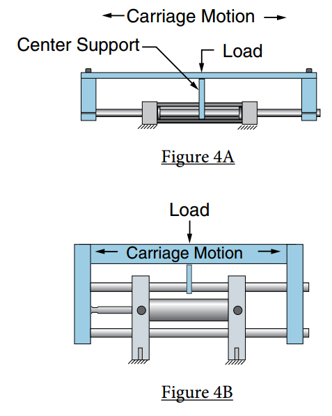
Rather than sizing up to a slide model with very large diameter guideshafts, you may be able to use a smaller model with the addition of the optional center support.
Safe Loading charts are usually included in slide manufacturer’s literature. The charts aid your design considerations by predicting maximum deflections at various strokes and loads.
About Fabco-Air
With operations housed in 61,000 sq. ft. in Gainesville, Florida, Fabco is dedicated to developing and providing advanced fluid power technology to give our customers the competitive edge they need in their field. 24/7 lights-out precision machining centers drive production, assure product quality and enable reliable delivery.
The content & opinions in this article are the author’s and do not necessarily represent the views of ManufacturingTomorrow
Comments (0)
This post does not have any comments. Be the first to leave a comment below.
Featured Product