A programmable Logic Controller is an industrial process control computer which has been "ruggedized" and adapted to control the manufacturing process. Almost all manufacturing processes are modernized and automated by adapting this technology to stay ahead of competition.
PLC Ladder Logic vs. Everything Else
Vaidyanath "Doc" Nanjundaiah | EZAutomation.net
 PLCs from different manufacturers can be programmed in various ways. IEC 61131-3 is the international standard for programmable logic controllers. The most common PLC programming methods used are:
- Relay Ladder Logic (RLL)
- Structured Text (ST)
- Function Block Diagram (FBD)
- Sequential Function Charts (SFC)
- Instruction List (IL)
A PLC system handles many numbers representing different types of information regarding the process. These processes or machine parameters can be anything from the status of the input or output devices, timers, counters, or other data values. These memory types can be used to store a variety of information and can be used inside various Relay Ladder Logic instructions. These are commonly known as “Tags”. Tags can be of different data types. Boolean (Discrete), Integers, Floating Point, Strings, and Time.
Ladder Logic
Ladder Logic is the main programming method used for PLC’s. It mimics the relay logic (combination of switches, relays, coils and contacts). The decision to use ladder logic as the main programming method was very strategic as it did not need much time to retrain engineers to adapt to this. The first generation PLCs were programmed with a technique that was based on relay logic wiring schematics. This eliminated the need to teach electricians, maintenance technicians and engineers how to program. To this day, ladder logic remains the most popular method to program a PLC.
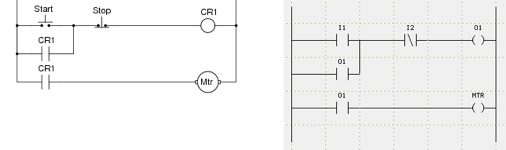
Below is a very simple motor control relay logic and its corresponding ladder logic. Relay Logic has a Start switch, Stop switch, Control Relay and Relay Coil (CR1) and a Motor (Mtr). Ladder logic shares similar look and feel as relay logic. But the physical switches and coils of relay logic are replaced with PLC’s memory location which are represented as Inputs (I) and Outputs (O).
| Motor Control Relay Logic | Motor Control PLC Ladder Logic |
 |
|
Ladder Logic is very simple to program, even an automation maintenance electrician can program or troubleshoot ladder logic. If it is a large PLC program, it might get a little tricky but still can be done.
Sturctured Text
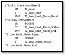
Structured Text is a text based programming language used to design PLC logic and it’s more like python Visual Basic or C. It uses less CPU memory and is good to move a lot of data and complex mathematical calculations. Complex PLC logic is easier to code and understand. Below is a sample:
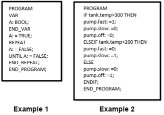
Some training may be needed to learn this. If you are not familiar with high level programming languages like C, Python or Visual Basic, it’s a little overwhelming for an electrician to learn this and maintain equipment on the fly. Structured Text can be programmer friendly but not Electrician or Maintenance Engineer friendly. You will have to know the Syntax, Expressions, Logical and Bitwise operators and Loops etc.
Function Block Diagram
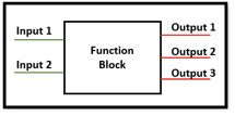 Function Block Diagram is used for PLC programs which are represented in the form of graphical blocks. It represents signals or data flow into the function block and when it is executed in the PLC logic, results in one or more outputs. Each function block is already pre-programed to do a certain function, the user has to plug in the inputs and outputs.
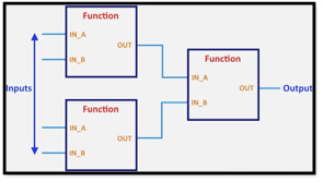 Function Blocks can have standard functions such as timers, counters, user defined blocks to obtain an average value, scaled value, finding out min and max values etc. It is easier to program but harder when trying to troubleshoot any issues while being online with the PLC. One cannot see the individual inputs or outputs being energized as the function block works as a whole and is highlighted as a whole element. Basic functions which are required to run the process like latching instructions, flip-flops and interlocks designed in function blocks are complicated to troubleshoot as compared to relay ladder logic.
Sequential Function Chart
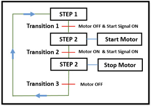 Sequential Function Chart is a graphical representation for depicting sequential behavior of a control system. It is mainly used for defining control sequences that are time or event driven. It interconnects steps, actions and transitions. It allows the description of the process to become the actual program. Basic working principle is; SFC will transition from Step 1 to Step 2 if all the steps above it are active and all conditions on the interconnecting transition are true.
The program can get very lengthy. If any modifications needed or any duplication or re-use of the same code in a different part of the logic is needed, extensive work is required to analyze and modify the changes. Also it gets very tricky for the maintenance engineers to analyze and maintain equipment if they do not know how to work with SFC.
Instruction List
 Instruction List is a low level, text based language that uses mnemonic instructions or they resemble assembly language programming. Each instruction begins in a new line and contains an operator such as Jump (JMP), Call Function Block (CAL), Return (RET) and mathematical operators like ADD, SUB, MUL and DIV etc. It is a low overhead language and it is executed faster as compared to other methods of programming a PLC.
This method is prone to run time errors and it can lead to infinite loops or illegal arithmetic operations. This method is 100% programmer friendly but has no benefit to the maintenance engineers or electricians to quickly analyze the code and troubleshoot during a machine shutdown unless they have formal training using this language.
Conclusion
 In many manufacturing plants, electricians take the ownership and maintain the equipment. They are generally not trained to use any programming languages. But they are well versed in ladder logic due to its similarity to hardwired relay logic. You might very well have a million dollar machine, but it is absolutely of no use if the electricians cannot troubleshoot the code written in other languages. Other PLC programming languages may be good for learning in a classroom environment, but not for industrial environment. Minimum downtime is the highest priority in all manufacturing plants. Process or the machine should always stay up and running. A combination of Relay Ladder Logic and Function Blocks is the best way to program a PLC as it is easier for both the programmer and electricians and maintenance personnel.
The content & opinions in this article are the author’s and do not necessarily represent the views of ManufacturingTomorrow
Comments (0)
This post does not have any comments. Be the first to leave a comment below.
Featured Product