Is Your Step Motor and Driver Contributing to the Inaccuracy of Your System?
Inaccuracies with Motors and Drivers: Who is the Culprit?
Contributed by | Lin Engineering
When it comes to precision in the motion control industry, there are many important factors that contribute to inaccurate steps. As a total system, engineers must become knowledgeable of their step motor as well as their driver/controller units.
Believing that all the inaccuracy lies within the motor is very common. From the step motor’s perspective there are tolerances to meet—both mechanically and electrically. Phase imbalance in Inductance is a large factor, as well as pole misalignment, rotor misalignment, inconsistent airgap between rotor and stator, stator and rotor tooth relationship, and torque stiffness to name a few. Although the list may seem overwhelming, it is not difficult to achieve and maintain.
Inductance relies on two factors: the coils and the rotor magnet. It is proportional to the number of turns per coil squared, therefore consistent inductance between phases is easy to achieve through correct winding of the motors. Most step motor manufacturers have automatic winding machines that can maintain this consistency. A proper rotor magnet must be used in order to maintain even inductance throughout the motor. As for the other specifications, most of it is mechanical and as long as manufacturers have reliable and good quality parts, consistent grinding of the rotor and stator, then an accurate step motor can be easily made. Lin Engineering holds a +/- 5% difference in Inductance between the two phases in a 2-Phase bipolar step motor. This tight tolerance will allow a step motor to perform with a +/- 1.5 arc minute error during 64 microstepping for a 0.9° motor. When specs are met, a step motor will do exactly what you tell it to do.
Now we are faced with the question: what exactly tells the step motor where to move and what to do? The answer: the driver and controller. Drivers give a specified amount of current (Amps) to each phase, dictating how many microsteps to take. Naturally, full stepping a motor outputs the best accuracy because this is how the step motor is mechanically made to move. The stator and rotor teeth are aligned in a comfortable state and the driver is outputting maximum current to the phases. As the step divisions become greater, as in higher microstepping, accuracy becomes more difficult to maintain.
Typical drivers are capable of 2x, 4x, 8x, 16x, 32x, 64x, 128x, and 256x microstepping, dividing the step motor’s full step by the respective number. For example: A 0.9° Step Motor in 64x microstepping mode will result in 0.014° for each step it takes. In order for this to happen, drivers must be able to divide the amount of current going to the motor phases in a precise matter.

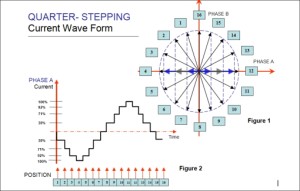
In the Figure 1 example , the phase diagram illustrates what Quarter Stepping (4x microstepping) looks like. The Current vs. Time graph illustrates the percentage of current a driver must output in order to maintain accurate microsteps.
To better understand the figure 1, look at Position 12. Using the percentage values, the coordinates for (Phase A, Phase B) are (100,0). The driver is outputting 100% of its current to Phase A while Phase B contains 0% of current. When the motor moves to Position 13, the coordinates now become (92, 38). The driver now outputs 92% of its total current to Phase A, and distributes 38% of its total current to Phase B. Analyzing each step in this way shows that Phase A and Phase B are offset by 90° on the sinusoidal current waveform. Figure 2 shows the sinusoidal waveform only for Phase A.
Looking at the driver’s perspective, the main component in outputting the correct amounts of current is the driver IC (or Integrated Circuit). The performance of a driver lies in the actual chip itself. Other factors that could lead to inaccurate performance are the internal MOSFETS, capacitors and resistors, circuitry layout, firmware (software), and adequate heat dissipation. Some may argue though, if the driver chip alone can create smooth and precise sinusoidal current waveforms, why is it a contribution to inaccurate steps?
Every step motor has a certain characteristic in performance. Some motors are made to perform well at low speeds resulting in high inductance values. Other motors are specifically used for high speed applications resulting in low inductance values. Step motors can accommodate for any motion profile by changing the windings in the coils to meet the mathematical formulas associated with speed, torque requirements, current, resistance, and inductance. Therefore, one driver will not perform the same amongst many step motors, and vise versa: one step motor will not output the same amount of torque with many different drivers. So what is an engineer to do?
The ultimate solution for getting the smoothest and most accurate system is to match the step motor to a driver. Currently, the closest the industry has seen to customization of drivers is to have adjustable functions for the output current. Some drivers have adjustable trimpots to alter the current waveform, others can adjust the gain, and some have evolved the ability to download specific sine tables to match the motor’s characteristic. Whatever the choice, let it be known that both the step motor and driver has the potential to contribute to inaccurate steps.
Example of an application requiring high accuracy:
Semiconducter Wafer Processing
![]()
The content & opinions in this article are the author’s and do not necessarily represent the views of ManufacturingTomorrow
Featured Product

