PowerInspect has dramatically improved our ability to locate and align parts with complex curved surfaces
CNC Inspection Software Reduces Time Needed to Machine Composite Parts
Contributed by | Autodesk
One of the toughest challenges faced by manufacturers of composite components is drilling and tapping holes that need to be closely aligned with embedded metallic hardspots. Aerodine Composites Group (Aerodine), experts in the design, manufacture, and application of high performance, light weight composite structures, overcame this challenge by using Autodesk PowerInspect software.
Aerodine’s team of repairmen and composite technicians work together to produce highly specialized alterations of existing composite structures as well as repair damaged components to original equipment specifications. The company has become the premier supplier of structural assemblies, research and development parts, ancillary support components and structural repair schemes to the high performance motorsport industry. This has enabled the company to build a vast catalog of damage scenarios, repair techniques, and manufacturing methods to ensure that safety is never compromised.

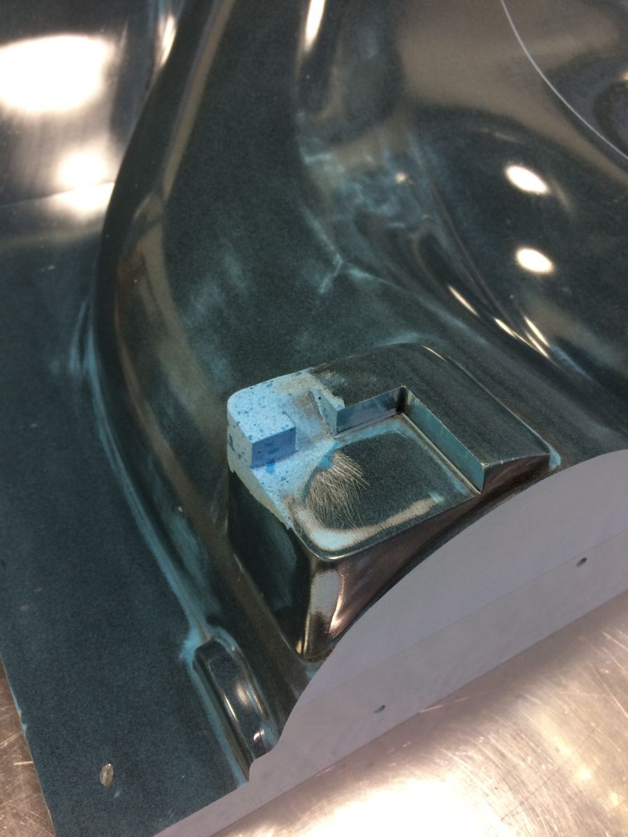
This image shows the area that was damaged during 4 years of storage and use. There was an area that was brokenoff that was prepped for bonding and repair putty was applied for machining later.
One of Aerodine’s recurring projects is the yearly production of 50 front wing assemblies for a large OEM automotive manufacturer who participates in the Indycar series. In the past, Aerodine produced these parts on manual machine tools but operators had difficulty aligning the machine spindle with the bushings buried in the part’s composite material. The result was that drill bits or taps frequently broke off when the tool crashed into the bushing. The machining time for typical parts was only 20 minutes but in this case, it took the operators between three and four hours to manually extract the broken drills and taps and repair the part.
Looking to improve on this operation, Aerodine engineers considered using computer numerical control (CNC) machining to produce these and other similar parts. The company purchased its first CNC machine - a DMS router with 5 feet by 10 feet by 4 feet travel – and was immediately successful in using the machine to produce parts with flat surfaces. However, every surface in the front wing assemblies and many other parts produced by Aerodine are curved so they are much more difficult to accurately align. Machine operators did the best they could but the inevitable misalignments caused drill bits and taps to continue to crash into the bushings embedded in the composites.
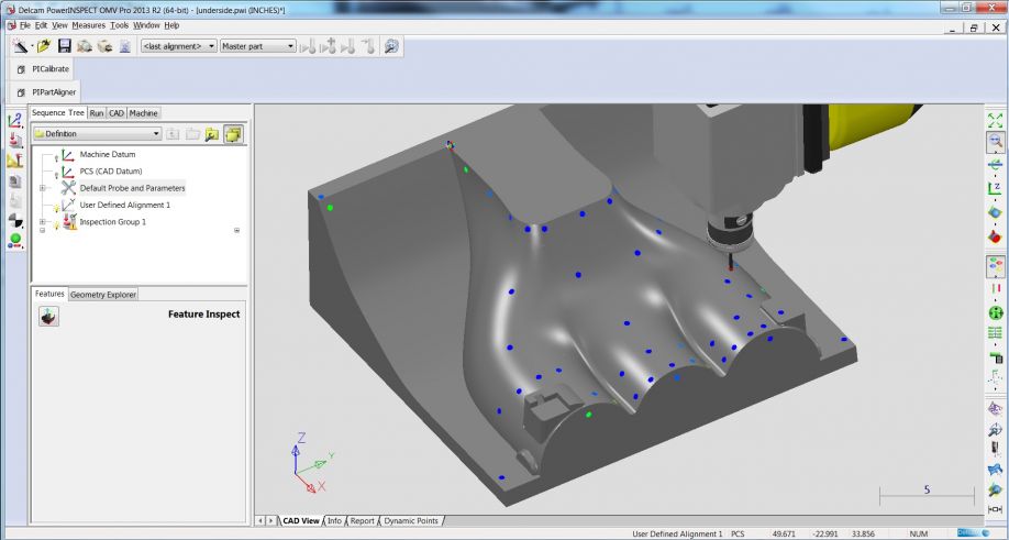
This image shows the results of the probing cycle brought back into PowerInspect before a best fit analysis. Thecolor blue indicates the results are lower than the tolerance band color of green. If the color is yellow to red theresults are higher than the tolerance band.
The company was already successfully using Autodesk PowerMill to produce CNC programs so they decided to look more closely at Autodesk PowerInspect, a part aligner tool that would help Aerodine accurately locate the part prior to machining. Using PowerInspect allows employees to open a CAD model of the part and use a mouse to select a series of points that can be used to accurately locate the model in 3D space. PowerInspect then generates a CNC program that runs on the machine tool with a touch probe in the spindle. Each time a new part is loaded onto the fixture, the machine tool control runs the CNC program generated by PowerInspect (which determines the actual position of the locator points), compares the results with the CAD model and performs a best fit analysis to determine the actual position of the part in the fixture. Finally, PowerInspect updates the CNC program to incorporate the actual position of the part.
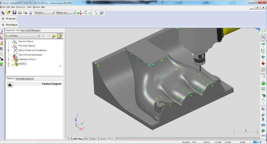
This image is after the best fit analysis
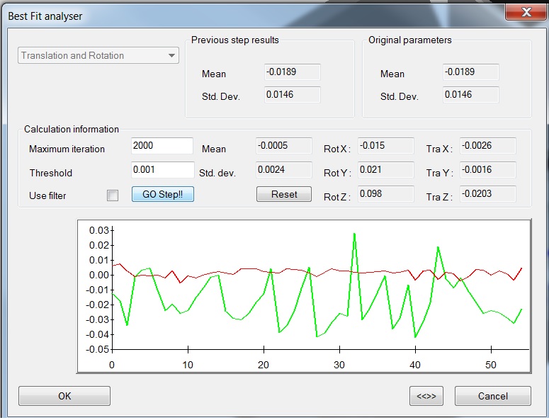
This image shows a graphical representation of the before and after best fit calculation and how the transform androtation were affected
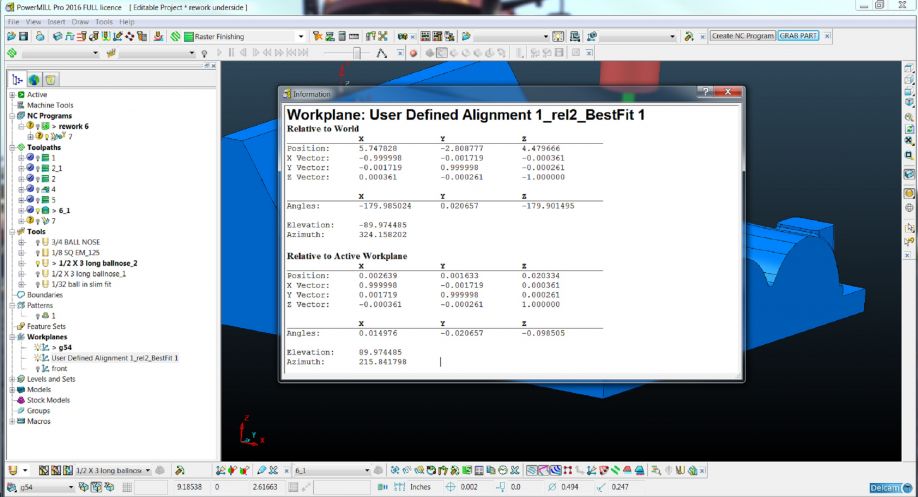
This is a screen shot of the query form exporting the NC file to the machine with the new best fit work plane. This aligns the machine to work piece seamlessly using the software to align the tool paths. Notice the use of the best fit alignment in the output section instead of G54.
G54 in this case is the offset used for the probing cycle and calculating initial tool paths. The output workplane field uses the "user defined alignment 1_rel2_Best Fit_1". This is where the shift occurs.
“By using PowerMill and PowerInspect together, we are able to all but eliminate the collisions that wasted so much time in the past,” said Kyle Castor, Patternmaking Manager for Aerodine. “At the same time Aerodine adopted PowerInspect, we also switched from the use of drills and taps to end mills and threads mills for machining the holes. The result is that nearly every part is produced in the specified cycle time of 20 minutes, a reduction of about 90% in cases where tools are difficult to remove.”
“PowerInspect has dramatically improved our ability to locate and align parts with complex curved surfaces,” Castor concluded. “The result is that we have been able to substantially reduce the time required for part alignment while delivering increasingly accurate products to our customers.”
The finished repair
The content & opinions in this article are the author’s and do not necessarily represent the views of ManufacturingTomorrow
Featured Product