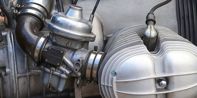
Injection timing is a critical variable in combustion engines. From tinkerers squeezing every bit of horsepower out of their ride to engineers seeking fuel efficiency breakthroughs, making adjustments here affects the entire engine system.
 Sensor Technology for Fuel Injection Timing

Emily Folk | Conservation Folks
The injection process must be tightly controlled if the engine is to receive the correct amount of fuel to function as it should. Today, this tends to be a digital process, with an engine control unit (ECU) receiving data from a series of sensors and adjusting fuel timing accordingly.
This is a look at the major sensor types in use today in fuel injection systems.
1. Mass Air Flow Sensors
A mass air flow (MAF) sensor is responsible for measuring the amount of air entering the engine. Air density changes with variations in altitude and ambient temperature. This means, for the engine to maintain the right ratio of fuel to air, continuous measurements are required.
Mass flow sensors appear in two varieties — hot-wire sensors and vane meters. The former is a newer and better technology. Hot-wire sensors are typically smaller, more responsive to minute changes and less expensive to incorporate.
2. Oxygen (O2) Sensors
Most cars built after 1980 come equipped with oxygen sensors. Each type of fuel has a different ideal ratio of air and gasoline during the combustion process. Oxygen sensors determine whether this ratio is being achieved at any given time.
Oxygen sensors work by monitoring the vehicle’s exhaust and measuring how much oxygen is present. Too little air results in leftover fuel. This is called a “rich” mixture. Too much air creates a “lean” mixture.
Both situations result in avoidable levels pollutants, including nitrogen oxide. A lean mixture might also compromise performance or damage the engine.
3. Throttle Position Sensors
Drivers introduce a host of variables of their own while driving, which is why modern vehicles come standard with throttle position sensors.
These sensors provide direct feedback to the fuel injection system by regularly measuring how far open or closed the throttle is and how quickly these changes are being made.
Essentially, throttle position sensors provide data about how a car is being driven and the power demands being placed on the engine in-the-moment. “Syncing” throttle behavior with fuel injection timing using this sensor ensures vehicles idle smoothly and accelerate on-demand.
4. Manifold Absolute Pressure (MAP) Sensors
Located near or within the vehicle’s intake manifold, MAP sensors measure the power load placed on an engine at any given time. The sensor compares these measurements against a vacuum for consistency.
MAP sensors are important because they report on the outside factors that contribute to a high engine load and higher demand for fuel throughput. For example, if a vehicle begins ascending a hill, the MAP sensor should register a low vacuum and a high engine load. In turn, the MAP sensor sends this data to the ECU, which requests more fuel.
5. Engine Coolant Temperature (ECT) Sensors
Like the other sensor technologies mentioned here, ECT sensors help bring conditions within and without the engine into harmony. In this case, ECT sensors — situated beside the vehicle’s thermostat — determine the impact of ambient temperature on the engine.
If an engine is cold, it requires two things to function well:
-
A greater quantity of fuel.
-
A higher idle for smoother ignition.
Warmer engines, on the other hand, need adjustments of their own. As the engine warms, the ECT sensor and ECU invoke cooling fans or make adjustments to ignition timing. When ignition timing is working as it should, the engine shouldn’t lose power when it’s called upon to perform. Poor ignition timing can result in engine knocking, power losses and engine damage.
Other Sensor Technologies
This has been a look at the most common sensors for fuel injection timing. There’s also a host of others under active development, many of which deliver the best results when used in tandem.
One scientific study explored a lineup of nonstandard but “quite effective” and “reliable” technologies, including the following:
-
Needle lift sensors: These deliver instant measurements of the beginning and end of fuel injection.
-
Piezoresistive pressure transducer sensors: These provide more accurate measurements of pressure changes within the engine.
-
Photo (or optical window) sensors: This type of sensor provides quick measurements of the start and duration of combustion.
Smart Technology Improves Fuel Injection
There are several advantages to studying fuel injection more closely and integrating sensors to provide on-the-fly data capture. Fine-tuning fuel injection improves the engine’s longevity, boosts engine power when it’s needed most and lowers the rate of fuel consumption.
These smart sensors bring Industry 4.0 principles, like data mobility, into the inner recesses of some of the most ubiquitous machines on earth — gasoline engines.
Applying the right technologies at this level makes our cars more efficient. Thanks to the fuel savings, it also means our world becomes an incrementally healthier place to live.
The content & opinions in this article are the author’s and do not necessarily represent the views of ManufacturingTomorrow
Comments (0)
This post does not have any comments. Be the first to leave a comment below.
Featured Product

