Marking of engineered assemblies, components and materials with identification numbers and other data is an essential element of modern manufacture. Until now, this has involved at least a small interruption in the production process for every unit marked.
 Moving Targets: Laser Marking on the Fly
Alastair Morris, Vice President | Pryor Technology Inc
As Industry 4.0 technology pushes manufacturing speed and efficiency to new heights, even momentary delays in production line flow are becoming unacceptable. When it comes to speeding up product marking, the answer is to laser mark on the fly - as Alastair Morris, Vice President of Pryor Technology Inc, explains.
Marking of engineered assemblies, components and materials with identification numbers and other data is an essential element of modern manufacture. Until now, this has involved at least a small interruption in the production process for every unit marked.
Conventional static marking methods such as scribing, or dot matrix cannot easily be applied in-line as part of a non-stop manufacturing process. High-speed, high-quality laser marking, fully automated and integrated with the production line, offers an advanced and well-proven alternative but still normally requires a moment’s delay for each mark. Those ‘moments’ soon add up to significant losses in productivity for high-volume or high-speed operations.
Marking on the move
As its name suggests, laser marking on the fly solves the time-loss problem by applying marks while the product continues to move along the line. It is especially useful for metal parts and raw materials.
To give an example, one manufacturer’s pressed bearing shells are now being marked at a rate of one per half second. Each mark, which contains a unique Data Matrix code for that individual component, takes just 0.2 of a second.
For strips, sheets or coils of raw material, travelling at hundreds of metres per second, marks can be made at chosen intervals as the product is being formed and processed.
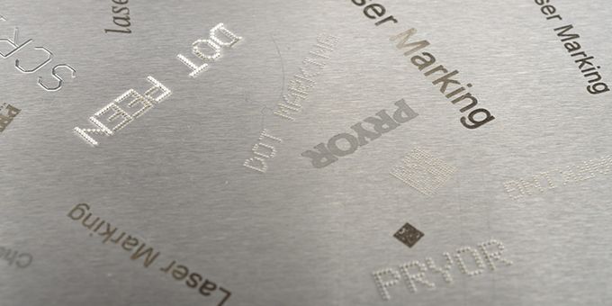
Marks can range from a simple day, batch or serial number to complex, individualised information required by a sophisticated data capture system. Further data can be added to the same component at different points along the line, providing a basis for analysis, assessment and improvement of production processes.
High-speed challenges
One obvious challenge is to make sure the mark is automatically located in the right place on each component by coordinating laser activity with line speed. Accelerations or decelerations, however small, can potentially disrupt this.
A typical marking window is around 0.16 of a square inch (1cm2), so as well as being accurate the laser needs to work quickly. Within that small time and space, it may need to produce marks containing a high complexity and quantity of data.
The material’s hardness and other physical properties can present further obstacles to creating marks with the right quality. In particular, the mark must be permanent and easy to read.
Lastly, the marking system must be supplemented by a verification method which can confirm correct placement and readability of each mark, again without any delay. Metal surface imperfections, scratches, marks and reflectivity can make this difficult.
Fast technology
Laser marking tracks the product as it moves along the line, using a light detector, through-beam or other physical sensor to detect when the product’s leading edge reaches a critical point. From there, activation of the laser beam is timed to coincide with the marking window, starting as it enters and finishing before it exits. An encoder wheel sitting on the conveyor or product monitors line speed, enabling the system to adjust for any fluctuation.
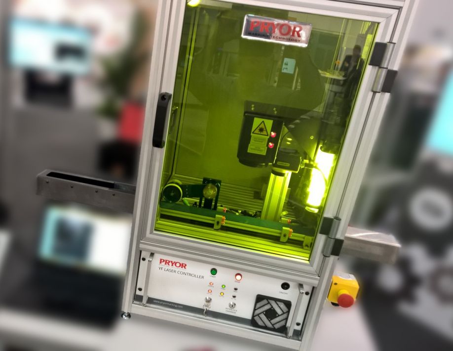
Using the latest high-energy fiber lasers, even highly resistant metals such as hardened steel can be permanently marked in just fractions of a second. This is achieved through a combination of flexible optical fibers, which maximise manoeuvrability, and powerful beams. The resulting mark quality matches that produced in a stationary situation.
Customised solutions
A key choice when specifying a system for marking on the fly is the laser’s power. With very high line speeds and hard metals, one of the more powerful lasers may be needed to make marks deep and clear enough in the time available. An alternative approach applicable in many cases is simply to extend the marking window.
Unless there is an opportunity to design laser marking into a manufacturing operation from its outset, the process will be customised to fit around the existing line and its equipment. This is largely a matter of selecting the marking system’s hardware according to the prevailing space constraints.
Once the laser system and its software are in place, manufacturers can start to reap the benefits. When every second counts, the substantial cycle time gains made possible by marking products without stopping the production line add up to a major advantage. When it comes to speeding up product marking, the answer is indeed to laser mark on the fly.
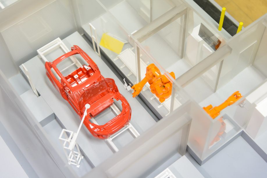
Pryor Marking Technology is a world leader in the manufacture and design of both traditional and innovative marking, identification and traceability solutions. Founded in 1849 in Sheffield, UK, a hub of manufacturing and the birthplace of stainless steel, the company’s success is built on providing solutions for all manufacturing industries, with extensive expertise in aerospace and automotive standards.
The content & opinions in this article are the author’s and do not necessarily represent the views of ManufacturingTomorrow
Featured Product