Pneumatic circuits can be safe when carefully examined and implemented. The designers can use the appropriate level of reliability based on their assessment of the risk and frequency of the potential risk.
Designing Safe Pneumatic Circuits
Erl Campbell | AVENTICS Corporation
The design of safe pneumatic circuits begins with a careful risk assessment. The process involves designers of all systems within a machine and/or process from mechanical to electrical. The first step is to look at the project and identify any potential hazards and risks for injury. The next step is to do a risk estimate and evaluation of each hazard. The engineers/designers can then develop the appropriate preventive measures to minimize the risk to acceptable levels. The standard developed within ISO (ISO 13849) outlines the process by which machine builders can develop their own standard for meeting the guidelines with the goal of making machines as safe as possible. The standard addresses the control of a machine and not the actual moving components (i.e. cylinders, actuators). Pneumatic circuits are usually only one part of a machine that could pose potential hazards.
The risk assessment of pneumatic circuits examines each actuator and its movement to determine if potential hazards (e.g. pinch points) exist. The hazards may already be addressed in the original machine design, as guarding or other obstacles may already be present. The easiest way to avoid the hazard would be to prevent access to the area, however the machine function and/or application may require access either when running the machine or in a maintenance mode. The design team works together to identify all areas where more control is required. The ISO standard focuses on the control aspect of the circuit, however at this point it would also be a good practice to ensure that the actuators used have been properly sized for the application. The proper sizing of the cylinders will also make the machine safer and more efficient. (Several pneumatic components manufacturers offer comprehensive online sizing tools to make this easier.) Once all risks have been identified and listed it will be time to move on to the risk estimation part of the process.
Risk estimation allows the design engineer to determine the category and performance level required for the safety circuit. The first question is what is the severity of the possible injury? High or low? The second question is how frequent is the exposure to the risk, and finally, is it possible to avoid the hazard if the safety circuit fails? Can you add additional guarding? The lower the risk, the lower the category and performance level required. The lowest category is “B” (basic) and increases to 1-4 with increasing reliability requirements for each. As the category increases, so does the achievable performance level. The performance level ranges from a-e and is based on the components used in the circuit. (see flow chart illustration Image 1)
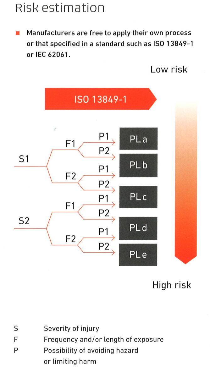
Image 1: Risk estimation flowchart
It is calculated based on statistical data from testing that the component manufacturer has done to determine the life - typically in cycles. The reliability of air valves is described using a B10 value which is number of cycles until 10 percent of the tested components fail. The reliability of electrical components such as cylinder limit switches is measured by MTTF or Mean Time To Failure. The failures may not all be dangerous failures so there are other values to reflect dangerous failures (i.e. B10d and MTTFd). The values will give you confidence in the reliability of the products you are selecting and you will need more reliable products as the required performance level required increases. Most pneumatic suppliers have this data available. Aventics has published data for many products with the IFA which is a European occupational safety and health organization. IFA also has free software to help with the calculations needed. The software is called SISTEMA and is available at www.dguv.de
Products and circuits meeting category 3 and 4 architecture requirements are increasingly required. The basic requirement for each is redundancy and monitoring of both channels. The monitoring is quantified as diagnostic coverage (DC) and listed as a percentage ratio of the rate of detected dangerous failures compared to the rate of all dangerous failures. All monitoring components that are used in the circuit will have a DC value. The values are used to calculate the DC average which is used to calculate the overall performance level (PL). Monitoring can be done directly or indirectly. An example of direct monitoring would be a sensor that would detect the position of a spool on a pneumatic directional valve and an indirect example would be a pressure switch downstream from the valve. Direct monitoring provides a higher DC value and will help to increase the performance level of the circuit. Another factor to consider is CCF or Common Cause Failure: this is an observational analysis of how components fail. The designer looks for possible reason why a component would fail. The environment could be at higher temperatures or the compressed air may not be properly filtered. The CCF is a point system based on several of these factors and when totaled for a given circuit will also be a factor in determining the PL. Category 4, which is the highest rating, requires a high DC value, high life cycle, and CCF observations with a PL of e.
At this point in the process the engineers know the category and performance level needed and can now design the circuit. The control circuit can be a single device that has been developed to perform a given safety function, however most require several pneumatic components configured in a logic circuit. Aventics has developed several circuits that have been approved by IFA that can be used to simplify the design and product specification. The most common pneumatic circuits used are Safe Exhaust, Safe Holding, and Protection against unexpected start-up. (see Image 2)
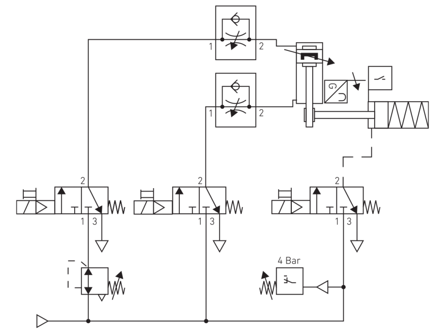
Image 2: Circuit diagram for holding or braking, any cylinder mounting direction, valve normally closed in starting position.
Safe Exhaust is probably the most common pneumatic circuit used for machine safety. The circuit is used to exhaust air from the machine or cylinder preventing trapped potential energy. Machine builders typically find that a Category 3 which can cover a Performance Level of a-d is required. The function can be accomplished with an integrated device or by using standard off the shelf pneumatic components the application can be optimized for the machine or application. The designer will use two 3 way valves in series to exhaust the system the valves can be monitored with sensors that detect spool or valve position or indirectly via flow or pressure sensors depending on the PL required.
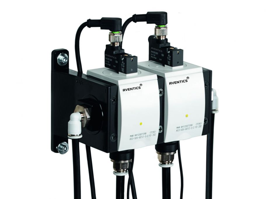
Image 3: Safe dual channel exhaust with 3/2 valves
Safe holding, and Protection against unexpected start-up circuits can be used to hold a load and ensure it does not move. The use of pressure operated check valves on cylinder ports can prevent air movement in a cylinder. The trapped pressure will prevent the cylinder from moving. Diagnostic coverage could be obtained from a pressure switch in the circuit. Another solution would be to use a rod lock which is typically a pneumatic device installed on the piston rod of the cylinder. The lock will only allow the cylinder to move when air pressure is sent to the port on the lock. Some manufacturers have a sensor to directly detect that the rod lock is engaged for increased diagnostic coverage.
Image 4: Holding unit (rod lock) series LU6, holding force of 12,000 N
Machine builders are asked to anticipate every scenario when their machine is running, not running and being serviced. They need to develop a well-documented process for making the machines as safe as possible. Pneumatic circuits can be safe when carefully examined and implemented. The designers can use the appropriate level of reliability based on their assessment of the risk and frequency of the potential risk. They can increase guarding when the design allows or develop a circuit to reduce the risk. The key to safe pneumatic circuits is to use proven and evaluated circuits, well-tried components that have been tested for life cycle data and properly size all components. Pneumatic suppliers are continuing to develop products to help designers implement these and other solutions such as integrated safe exhaust, dynamic and static rod locks, and position transducers that can give feedback on a cylinder’s position throughout the full stroke. The goal is to make the machine safer, but added benefits include making the machine more reliable and increasing machine efficiency.
The content & opinions in this article are the author’s and do not necessarily represent the views of ManufacturingTomorrow

EMERSON
Emerson's industry-leading portfolio enables us to identify and confront the challenges of an increasingly complex and unpredictable marketplace from a position of strength, driving near- and long-term value as a trusted partner for our customers.
![]()
![]()
![]()
![]()
Other Articles
Maximizing OEE with Smart Selection of Electric Linear Actuators
The Benefits of Dust Collector Pulse Valves
Case Study - Fast Pneumatics Cuts Cycle Time in Half
More about EMERSON
Featured Product