The vision system sends coordinates to the robot so it can be gripped by the robot regardless of position.
Contributed by | ST Robotics
In normal robotics the object must be in a known position - a holder or feeder or gate etc. ST Robotics offer a low cost vision system for determining the position of an object which is not in a repeatable position in the usual way. The vision system sends coordinates to the robot so it can be gripped by the robot regardless of position.
It comprises a Matrox GigE camera (1920x1448 pixels), C-mount lens with zoom, focus and exposure control and LED lighting. The harware and software are easily installed in your own PC. The system includes all cables, CAT6 cable and camera power supply, all ready to go.
The camera and lighting should be mounted by the user about half a metre above the work area. The workspace should be shielded from stray lighting such as sunlight or fluorescent tubes. The camera is then calibrated to a disc and a rectangle of known size.
This is a high accuracy system that can measure to 0.1mm.
How does it work?
The PC can connect to the robot controller in the usual way running RobWin. A second serial channel (or USB converter) connects to the robot controller second serial channel. This permits you to write your program in RobWin and test out communication with the camera as you go along.
Software is provided for the controller i.e. commands or words that you can use. The simplest command is just VISION. This then sends a command to the vision system. The camera takes measurements and sends back the position of the object in X and Y coordinates plus it's angle. The robot now knows where the object is and can pick it up rotating the wrist as necessary.
Results box
Shown with the RobWin command window inset.
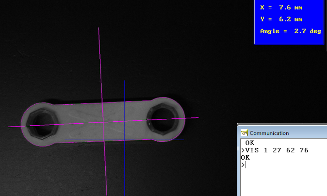
Final coordinates displayed and also sent to the robot. The RobWin window shows the simple command VIS and the results back from the vision system. the leading 1 means successful measurement.
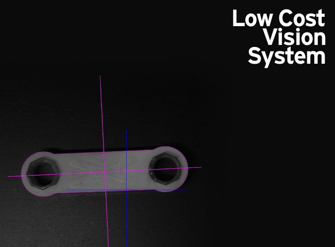
The blue cross is the camera center (0,0). The mauve cross is the centre of the object, shown in this example as 7.6mm on X and 6.2mm on Y from the camera center with the object tilted to 2.7 degrees. Note that the centre of the picture is not X=0,Y=0 of the robot. These are relative positions. The robot system therefore adds offsets to reach the exact position required.
This video shows a typical application. A backing sheet feeds along a conveyor. The robot picks up a box and must place it on the backing sheet central to within 1mm. The vision system tells the robot what the X-Y position and angle of the backing sheet. The robot adjusts the box accordingly and lowers onto the sheet. Four example show how even extreme angles are handled by the system.
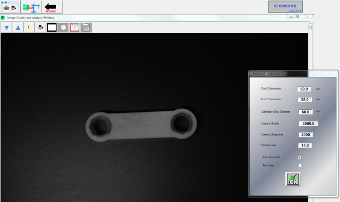
Parameters screen showing measured size of the object and camera settings.
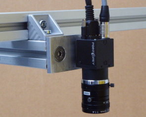
Camera mounted on robot
This is another way of using the camera. It is more versatile because the robot can position the camera anywhere in the workspace but must be carried everywhere the robot goes which might not be convenient.
Vision system controls
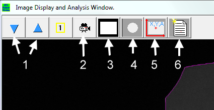
- zoom in/out
- live view
- binary (white on black)
- calibration
- measurement window (normal window)
- analysis (size of object etc)
About ST Robotics
Manufacturer of low cost bench top robot arms with a unique approach to robotics.
We have a range of robot arms for routine testing, manufacturing, sample handling, education and many others. Our robots are not only affordable but are incredibly easy to use - anyone can apply and program an ST robot regardless of experience or lack of it thanks to our acclaimed manuals and tutorials and unlimited free technical support. At the same time our unique language RoboForth permits complicated programs requiring intricate motions and extensive I/O, interfacing with and even controlling other devices. ST robots are maintenance free and abuse proof and are supplied with all necessary cables, and software, plus a choice of optional pneumatic and electric grippers. Unpack it, set it up and see your first programmed motions in a matter of minutes.
The content & opinions in this article are the author’s and do not necessarily represent the views of ManufacturingTomorrow
Featured Product