As technology advances, components become smaller and more compact which requires specific automation techniques and maintenance. Transfer mechanisms require high versatility in its capabilities.
 Automation Design Tips: Transferring with Rollers
Carlicia Layosa | MISUMI USA, Inc.
When designing certain elements of automation there are a number of factors to consider, one element of automation is transferring, specifically with rollers. As technology advances, components become smaller and more compact which requires specific automation techniques and maintenance. Transfer mechanisms require high versatility in its capabilities.
GENERAL PRINCIPLES OF ROLLER TRANSFER
The principle of transfer is the control of the frictional force to move the individual loads being transferred. In practice, the rotational force of the drive motor for transport is transmitted to the feed rollers. Due to the weight of the pieces acting on the feed rollers and the coefficient of friction in the feed rollers, the frictional force is produced in the tangential direction. The reaction force to the frictional force is how each piece is transferred per the figure below, Figure 1.
![]()
![]()
Figure 1 Principle of Roller Transport
Therefore, as a rule, such mechanical design is required that can cause the frictional force to be generated at the point of contact between individual pieces and feed rollers to ensure steady transfer.
To minimize any possible effects on the transported item such as bending, the weight must be equalized on the rollers therefore increasing the number of feed rollers would be a solution to stabilize the reaction force. The figure below illustrates that when the number of rollers increases, the more stable the weight of the item will be upon transfer.
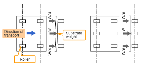

Figure 2 Weight Stabilization
Another method to minimize effects on the transported item is to install rollers that have a larger coefficient of friction. For example, the item or substrate being transferred could be sliding on the rollers, to combat this, installing urethane rollers would be a possible solution. Rubber O-rings and urethane rubber can increase friction to the roller. See figure 3 for an example, on the right shows the roller with an O-ring for added friction.
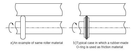

Figure 3 Adding an O-ring to increase friction
Now that design principles of rollers have been reviewed. Let’s take a look at three roller transport systems.
ROLLER TRANSPORT SYSTEMS
1 – Two Row Configuration of feed rollers (Fig.4-a)
If the transported materials vary greatly in deflection or the O-rings are worn partially or unevenly, poor or inconsistent contact between the material and rollers can result, leading to possible damage or bending of the material. In the designing of roller materials and diameters, consideration may be given so as to make the feed rollers at the respective ends serve as main rollers and the feed rollers in the middle act as sub rollers, thereby ensuring stable transfer.
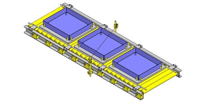
2 – Three Row Configuration independent arrangement of feed rollers (Fig.4-b)
In order to minimize the effects of deflection of thin materials in the two row configuration, the items are supported and transferred on the rollers arranged in three rows instead of two. By installing rubber O-rings on the outer circumference of rollers to transmit the frictional force, increased and stabilized friction coefficient and enhanced ease of maintenance are expected.
3 – Three Row Configuration of feed rollers connected through one ring (Fig.4-c)
This design can involve the following problems: direct susceptibility to any differences (related to friction coefficient) between the three O-rings in contact with the transferred items, increased parts cost, and/or increased staff-hours for assembling and/or maintenance for stabilized tension of O-rings.
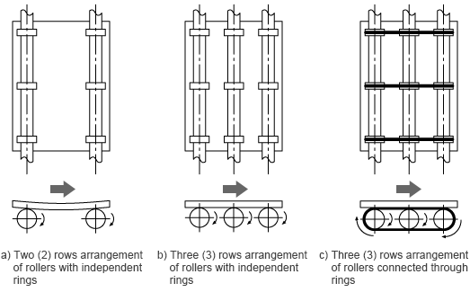

Figure 4 Roller Configurations
Among the three configurations, the second one shown in Fig.4-b is more favorable for transfer of materials with reduced thickness and weight.
.png)
One issue that can occur is the item/substrate not remaining in a straight path on the rollers. The frictional force must be equalized at all contact points between the item and rollers. In order to eliminate possible effects of unstable force for transport due to any deflected substrates, consideration may be given to increase the number of substrate support points, thereby ensuring stabilized loading and frictional force at each point of contact with a roller. In practice, however, this solution alone cannot necessarily equalize the frictional force at all points of contact.
To guide the loads being transported to move straight on the line, the direction of action of frictional force for transport must be made straight. There is no correlation between increasing the number of roller support points for substrates and making the direction of action of frictional force for transport straight. If the frictional force acting on the feed rollers becomes unbalanced, the loads being transported fail to move straight but their transport direction changes, resulting in transport problems.
Figure 5 below illustrates the possible movement of materials being transported when the frictional force acting on the feed rollers differs between roller positions; the frictional force is largest at the leftmost position followed by the middle and rightmost positions.
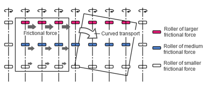

Figure 5: Curved transport of the material
Here are a few possible reasons why the frictional force becomes different:
1 – A bent shaft connecting the feed rollers
2 – Partially or unevenly worn feed rollers
3 – Inclined horizontal reference for the transfer machines
Therefore, in addition to the adoption of the three-row independent feed roller configuration, proper provisions must be made to equalize the frictional force on the feed rollers supporting the substrates.
In order to achieve the optimum frictional arrangement of rollers. Optimal allocation of the frictional force acting on individual rollers should be considered based on the concept of making the direction of action of frictional force easy to become straight even if the substrate support positions vary, by controlling the friction coefficient at each substrate support point of a roller.
One way to accomplish this is to use rollers made with O-rings and plastic. If these types of rollers are arranged alternately, the varying degrees of friction of each roller will assist in ensuring that the material/substrate stays straight. The rollers will support a flat plate at a total of 9 points, and at 5 or 4 of the 9 points, the frictional force is transmitted, thus ensuring stable transfer.
The plan of arrangement of rollers with O-rings (Fig.6-Pattern A) provides agreement with the points for measurement of the thickness of flat plates, showing a fundamental pattern for flat plate support.
The relation between substrates and roller positions in Pattern B, different from Pattern A, in which substrates move on the transfer line, is shown (in Fig.6-Pattern B).
Combined adoption of two roller arrangement patterns, A and B, facilitates linear movement of each substrate under the well-balanced distribution of frictional force.
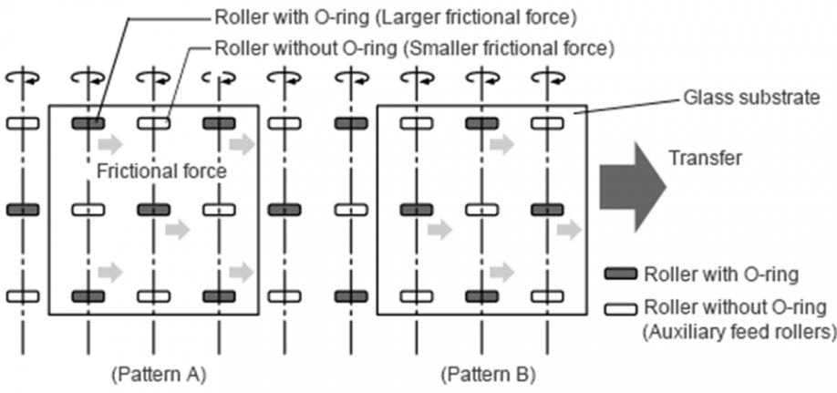

Figure 6: An Example Optimal Roller Placement
It is all a balancing act to keep materials/substrates straight on a transfer path with rollers. We hope the design tips presented here assist you in your transferring with rollers applications!
The content & opinions in this article are the author’s and do not necessarily represent the views of ManufacturingTomorrow
Comments (0)
This post does not have any comments. Be the first to leave a comment below.
Featured Product