If you are new to the 3D printing industry, dont rush to buy the least expensive printer. Some of these might be too simple for your manufacturing requirements and lack some important features like print bed auto-calibration or Wi-Fi connectivity.
Len Calderone for | ManufacturingTomorrow
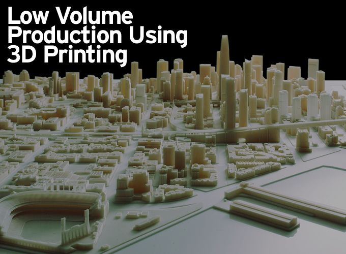
3D printing—additive manufacturing—was originally designed for rapid prototyping. But now, it is used for actual manufacturing. Engineers not only use this process for prototypes, but they are also using 3D printing for actual manufacturing. The 3D process allows customization, design freedom, easier assembly, and for the small manufacturer, it allows for low cost, low volume production.
Traditional processes, such as injection molding, are used more for large scale manufacturing. 3D printing is more economical for small volumes. 3D printing is reshaping product development and manufacturing. Using the 3D printing process, designers and engineers save time and money, while conceptualizing and testing prototypes. This is invaluable, as it saves time, while presenting the opportunity to create an extremely accurate model of how a new product will look.
For a small manufacturer, the most expensive and labor intensive part of product development is the production of the tooling. 3D printing eliminates these costs, as it removes the need for tool production, which also cuts lead times and labor.
A side benefit of using the 3D process is protecting the environment, as additive manufacturing is energy efficient. The process uses up to 90% of standard materials, thereby reducing waste.
3D printed tooling reduces the injection molding process timeline from months and weeks to days and hours. It is now possible to get functional, testable injection molded models, and low-volume production parts faster than ever before. When speed is important, usable prototypes can be used for testing impact resistance, chemical resistance, water intrusion, and flexibility. Additive manufacturing is fast and versatile because the tools can be 3D printed in less than a day.
The advantage of 3D printing molds over the standard steel or aluminum molds is the lead time and cost. It takes many weeks to build typical tooling molds. Mistakes in the mold design do not show until after machining. Multiple design changes go from the designer to the tool engineer until the final mold design and quality are achieved. This adds costs and increases the time to market.
If a manufacturer produces less than 1,000 pieces, 3D manufacturing will optimize production. In manufacturing, the more that you produce, the lower the cost becomes. This is especially true when manufacturing plastic items. Injection molding is very expensive when the production is low. This is where 3D printing becomes feasible, as the production rate increases up to 20 times and the cost is lower. A company can purchase around twenty 3D printers for the cost of one injection molding system. Not only can the company raise its production rate, but it will use labor more efficiently.
.jpg)
Direct Metal Laser Sintering (DMLS) utilizes a precise, high-wattage laser to micro-weld powered metals and alloys to form fully functional metal components, using CAD data. Using materials, such as aluminum, stainless steel and titanium, DMLS parts are strong, tough and heat resistant. Complex metal parts that previously were hard or impossible to fabricate with other manufacturing processes are now practical.
.jpg)
Stereolithography is the oldest 3D printing method; yet it’s still being used today. A mechanical engineer, who needs to verify if a part can fit into a design, can use stereolithography to assist turning models into real 3D printed objects by converting liquid plastic into solid 3D objects.
Most printing techniques require a CAD file to process the object. This file contains information about dimensional representation of an object. The CAD file must be converted into a format that a printing machine can understand, which is STL, commonly used for stereolithography. The STL file has the information for each layer of printing.
.jpg)
DLP is a process similar to stereolithography in that it is a 3D process that works with photopolymers. DLP uses a more conventional light source, such as an arc lamp. Using a Digital Micro-mirror Device (DMD), which is applied to the entire surface of the vat of photopolymer resin in a single pass, makes DLP faster than stereolithography.
Selective Laser Sintering (SLS) is the rapid prototyping technology of choice for a range of functional prototype applications, including those with snap fits, living hinges and other mechanical joints. The ability of SLS to produce several pieces at one time also makes the process a good choice for Direct Digital Manufacturing (DDM) of products requiring strength and heat resistance.
SLS uses high power CO2 lasers to fuse plastic, metal or ceramic powder particles together, layer-by-layer, to form a solid model. The system consists of a laser, part chamber, and control system.
The part chamber consists of a build platform, powder cartridge, and leveling roller. A thin layer of material is spread across the platform where the laser traces a two-dimensional cross section of the part, sintering the material together. The platform then descends a single layer thickness and the leveling roller pushes material from the powder cartridge across the build platform, where the next cross section is sintered to the previous. This process is repeated one slice at a time until the part build height is completed.
.jpg)
Fine metal powder for SLS
Once the model is complete, it is removed from the part chamber and finished by removing any loose material and smoothing the visible surfaces. Part support is accomplished by the un-sintered powder that surrounds the parts during processing.
MultiJet Printing (MJP) is a rapid prototyping process that provides a quick turnaround for smooth, high-resolution, hard plastic parts with complex geometries. The process consists of UV bulbs and photopolymer materials.
The printed parts have smooth surfaces and exceptional details with mechanical properties suitable for study models, and form & fit testing. The MJP process consists of a print head, platform, UV lamp, and a planarizer. A 3D CAD file is also used for this process.
.jpg)
The printer then prints each layer of the file in UV curable liquid plastic onto a flat platform. The wax support material is also jetted to fill voids and other non-freestanding features. UV lamps solidify the materials, creating a fully cured plastic or wax part.
MJP is an additive manufacturing process that prints thin layers of UV curable liquid plastics and wax support materials to create high resolution fully cured plastic parts.
If you are new to the 3D printing industry, don’t rush to buy the least expensive printer. Some of these might be too simple for your manufacturing requirements and lack some important features like print bed auto-calibration or Wi-Fi connectivity. Determine what the printer will be used for, as some of the printers available on the market are suitable only for a specific use. Take the time to do due diligence before making a commitment.
For additional Information:
- https://www.3dhubs.com/best-3d-printer-guide
- http://www.stratasys.com/~/media/Main/Secure/White%20Papers/Rebranded/SSYS_WP_in_house_vs_outsource.pdf
- http://studiofathom.com/wp-content/uploads/FATHOM_SolidWorks_MultiMaterial_F001_2014.pdf
- http://www.slideshare.net/MustafaZJawadwala/3d-printer-technical-paper
|
Len Calderone - Contributing EditorLen contributes to this publication on a regular basis. Past articles can be found with an Article Search and his profile on our Associates Page He also writes short stores that always have a surprise ending. These can be found at http://www.smashwords.com/profile/view/Megalen.
|
 |
The content & opinions in this article are the author’s and do not necessarily represent the views of ManufacturingTomorrow
Comments (0)
This post does not have any comments. Be the first to leave a comment below.
Featured Product